element14 Community
element14 Community
    Register Log In
  • Site
  • Search
  • Log In Register
  • About Us
  • Community Hub
    Community Hub
    • What's New on element14
    • Feedback and Support
    • Benefits of Membership
    • Personal Blogs
    • Members Area
    • Achievement Levels
  • Learn
    Learn
    • Ask an Expert
    • eBooks
    • element14 presents
    • Learning Center
    • Tech Spotlight
    • STEM Academy
    • Webinars, Training and Events
    • Learning Groups
  • Technologies
    Technologies
    • 3D Printing
    • FPGA
    • Industrial Automation
    • Internet of Things
    • Power & Energy
    • Sensors
    • Technology Groups
  • Challenges & Projects
    Challenges & Projects
    • Design Challenges
    • element14 presents Projects
    • Project14
    • Arduino Projects
    • Raspberry Pi Projects
    • Project Groups
  • Products
    Products
    • Arduino
    • Avnet Boards Community
    • Dev Tools
    • Manufacturers
    • Multicomp Pro
    • Product Groups
    • Raspberry Pi
    • RoadTests & Reviews
  • Store
    Store
    • Visit Your Store
    • Choose another store...
      • Europe
      •  Austria (German)
      •  Belgium (Dutch, French)
      •  Bulgaria (Bulgarian)
      •  Czech Republic (Czech)
      •  Denmark (Danish)
      •  Estonia (Estonian)
      •  Finland (Finnish)
      •  France (French)
      •  Germany (German)
      •  Hungary (Hungarian)
      •  Ireland
      •  Israel
      •  Italy (Italian)
      •  Latvia (Latvian)
      •  
      •  Lithuania (Lithuanian)
      •  Netherlands (Dutch)
      •  Norway (Norwegian)
      •  Poland (Polish)
      •  Portugal (Portuguese)
      •  Romania (Romanian)
      •  Russia (Russian)
      •  Slovakia (Slovak)
      •  Slovenia (Slovenian)
      •  Spain (Spanish)
      •  Sweden (Swedish)
      •  Switzerland(German, French)
      •  Turkey (Turkish)
      •  United Kingdom
      • Asia Pacific
      •  Australia
      •  China
      •  Hong Kong
      •  India
      •  Korea (Korean)
      •  Malaysia
      •  New Zealand
      •  Philippines
      •  Singapore
      •  Taiwan
      •  Thailand (Thai)
      • Americas
      •  Brazil (Portuguese)
      •  Canada
      •  Mexico (Spanish)
      •  United States
      Can't find the country/region you're looking for? Visit our export site or find a local distributor.
  • Translate
  • Profile
  • Settings
Experts, Learning and Guidance
  • Technologies
  • More
Experts, Learning and Guidance
Ask an Expert Forum Is my 74HC08 bad?  (Weird results in Make: Electronics experiment 21)
  • Blog
  • Forum
  • Documents
  • Leaderboard
  • Files
  • Members
  • Mentions
  • Sub-Groups
  • Tags
  • More
  • Cancel
  • New
Join Experts, Learning and Guidance to participate - click to join for free!
Actions
  • Share
  • More
  • Cancel
Forum Thread Details
  • State Suggested Answer
  • Replies 14 replies
  • Answers 9 answers
  • Subscribers 289 subscribers
  • Views 3956 views
  • Users 0 members are here
  • make electronics
Related
See a helpful answer?

Be sure to click 'more' and select 'suggest as answer'!

If you're the thread creator, be sure to click 'more' then 'Verify as Answer'!

Is my 74HC08 bad?  (Weird results in Make: Electronics experiment 21)

opalko
opalko over 4 years ago

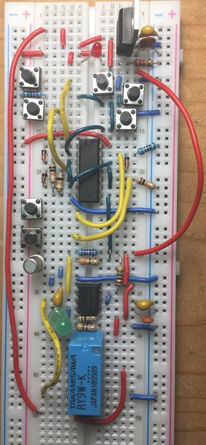
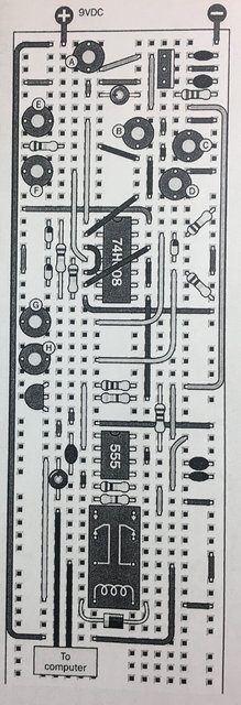
So I have built the "combination lock" from Charles Platt's Make: Electronics experiment 21 a couple of times now without getting it working correctly.  The schematic for the lock is below. The experiment is supposed to take a combination (pressing buttons E, F, G, H in order) to unlock the lock and provide power at the leads marked "to computer".  The buttons E, F, G, H are tied to a 74HC08 Quad AND chip with each button tied to an AND gate.  Each gate is unlocked in series by providing logical high as input from the previous button.  That is how it is supposed to work, but mine does not!  Using a logic probe, mine always has logic high on both inputs of button E so it seems to have no effect.  Pressing buttons F and G then unlock the circuit (sending high to H) which does not appear to need be pressed at all. One other weird thing is that I can occasionally start with a logical low at AND gate E if I disconnect and reconnect the green jumper tied to pin 2 on the 74HC08 from the 10K resistor to the same AND gate input, but not always.


I have taken the 74HC08 out and tried each AND gate separately and they all appear to work correctly independent of experiment 21.  But put it back into my circuit and logic high is always present on both inputs of the gate button E is attached to before I ever get started.  Do I just need another chip to try this with (I don't have one)?  Any help on how to troubleshoot further is appreciated!!  Note: I have removed switch A in mine as it was too much trouble to keep it pressed while troubleshooting and just substituted a jumper.


Regards,
Robert Opalko

Schematic

Circuit as built

Platt's image of how to build circuit

  • Sign in to reply
  • Cancel

Top Replies

  • jw0752
    jw0752 over 4 years ago +2 suggested
    Hi Robert, Check the voltage to ground on both sides of the 10K resistor that ties pin one to ground. This resistor should pull pin one low unless the E button is pushed. If it doesn't you probably have…
  • DAB
    DAB over 4 years ago +2 suggested
    The HC logic is very sensitive to levels so make sure each input has a pull up resistor so that they have a well defined state transition. It looked to me like there were some inputs directly attached…
  • dougw
    dougw over 4 years ago +2 suggested
    Logic gates can be unpredictable or undefined as power is applied to the circuit. If the gate output is even momentarily high during power up, it will latch up the gate in the high state. Pushing switch…
Parents
  • dougw
    0 dougw over 4 years ago

    Logic gates can be unpredictable or undefined as power is applied to the circuit. If the gate output is even momentarily high during power up, it will latch up the gate in the high state. Pushing switch B, C, or D should unlatch it. Placing a small capacitor across these switches may keep the gate input low long enough to ensure uneven thresholds don't define the initial state during power up.

    • Cancel
    • Vote Up +2 Vote Down
    • Sign in to reply
    • Verify Answer
    • Reject Answer
    • Cancel
Reply
  • dougw
    0 dougw over 4 years ago

    Logic gates can be unpredictable or undefined as power is applied to the circuit. If the gate output is even momentarily high during power up, it will latch up the gate in the high state. Pushing switch B, C, or D should unlatch it. Placing a small capacitor across these switches may keep the gate input low long enough to ensure uneven thresholds don't define the initial state during power up.

    • Cancel
    • Vote Up +2 Vote Down
    • Sign in to reply
    • Verify Answer
    • Reject Answer
    • Cancel
Children
  • opalko
    0 opalko over 4 years ago in reply to dougw

    Thank you for this!  Pressing one of the buttons B, C, or D did indeed reset gate 1 to a logic low enough that gate 1 worked correctly!


    However, I still have a problem in that the relay is triggered by only pressing buttons E, F, and G.  G should really trigger what I will call gate H (pins 8, 9, 10) which then triggers the relay; but in mine the relay is triggered after E, F, G.  Gate 4 output maintains a logic low even when the relay is activated.  I should also note that when I have a logic probe attached to pin 10 to watch the state of gate 4 where the 10K resistor is attached, the sequence works correctly! E, F, G, H -> unlock   ....  Still lost!  Cheers

    • Cancel
    • Vote Up +1 Vote Down
    • Sign in to reply
    • Verify Answer
    • Cancel
  • dougw
    0 dougw over 4 years ago in reply to opalko

    That behavior would be explained if the 10K resistor was not making good contact with the input to gate 3.

    The extra load or capacitance of the probe prevents the (floating) input from going high.

    Without the logic probe, the input is floating and a little capacitive coupling to the other input can cause it to go high when gate 4 goes high.

    Try to ensure that resistor is making good contact to the input pin.

    • Cancel
    • Vote Up +1 Vote Down
    • Sign in to reply
    • Verify Answer
    • Reject Answer
    • Cancel
  • opalko
    0 opalko over 4 years ago in reply to dougw

    So I checked all the resistors and made sure they were making good contact - they were and I didn't see any difference in the behavior of the circuit, so I rebuilt it from scratch one more time!  This time I cut new jumpers for a few of the connections (not all), but used the same resistors and diodes.


    The very first time I tried the circuit it did the same thing: E, F, G -> relay activated & LED lit.  The second time I tried it, I made it through the combination E, F, G, H -> relay & LED activated.  Tried a third and fourth time with all 4 buttons and it unlocked. After all that time I had to make video proof (google photos link)!  Success? Well, I don't know.  I then tried different button combinations and got weird results.  A few times starting with pressing button G (gate 3) then H (gate 4) I could get the relay & LED to activate. Other times that didn't work and would only take the combination  E,F,G,H..


    I've built all the other circuits in the book without this kind weirdness but then again this is the first logic chip used so far.


    Cheers

    • Cancel
    • Vote Up +2 Vote Down
    • Sign in to reply
    • Verify Answer
    • Reject Answer
    • Cancel
  • DAB
    0 DAB over 4 years ago in reply to opalko

    You might be getting glitches on your buttons.

    They would probably work better with some debouncing components.


    If you have an oscilloscope handy, look at the inputs to the gate when you press the buttons.


    If you see a lot of jitter in the signal, put a low pass filter on them to take out the high frequency noise.


    DAB

    • Cancel
    • Vote Up +2 Vote Down
    • Sign in to reply
    • Verify Answer
    • Reject Answer
    • Cancel
  • opalko
    0 opalko over 4 years ago in reply to DAB

    I don’t have a scope but it may be time to get one!  Also haven’t learned filters yet; I have some reading to do - thank you.

    Cheers

    • Cancel
    • Vote Up +1 Vote Down
    • Sign in to reply
    • Verify Answer
    • Cancel
  • Andrew J
    0 Andrew J over 4 years ago in reply to opalko

    Dab is likely to be right.  I’ve done those builds and they all work.  I found that on some of them, it was necessary to add some capacitance to debounce buttons and stabilise the cheap power supply I was using - the book says to buy a cheap wall wart supply, cut the connector off, strip the wires and use those.  Even Charles, the author, has said “I thought the cheap supplies would have gotten a lot better by now” - they haven’t!  I’ve even had circuits affected just by holding a finger near one of the jumper wires!!

    • Cancel
    • Vote Up +1 Vote Down
    • Sign in to reply
    • Verify Answer
    • Reject Answer
    • Cancel
element14 Community

element14 is the first online community specifically for engineers. Connect with your peers and get expert answers to your questions.

  • Members
  • Learn
  • Technologies
  • Challenges & Projects
  • Products
  • Store
  • About Us
  • Feedback & Support
  • FAQs
  • Terms of Use
  • Privacy Policy
  • Legal and Copyright Notices
  • Sitemap
  • Cookies

An Avnet Company © 2025 Premier Farnell Limited. All Rights Reserved.

Premier Farnell Ltd, registered in England and Wales (no 00876412), registered office: Farnell House, Forge Lane, Leeds LS12 2NE.

ICP 备案号 10220084.

Follow element14

  • X
  • Facebook
  • linkedin
  • YouTube