element14 Community
element14 Community
    Register Log In
  • Site
  • Search
  • Log In Register
  • About Us
  • Community Hub
    Community Hub
    • What's New on element14
    • Feedback and Support
    • Benefits of Membership
    • Personal Blogs
    • Members Area
    • Achievement Levels
  • Learn
    Learn
    • Ask an Expert
    • eBooks
    • element14 presents
    • Learning Center
    • Tech Spotlight
    • STEM Academy
    • Webinars, Training and Events
    • Learning Groups
  • Technologies
    Technologies
    • 3D Printing
    • FPGA
    • Industrial Automation
    • Internet of Things
    • Power & Energy
    • Sensors
    • Technology Groups
  • Challenges & Projects
    Challenges & Projects
    • Design Challenges
    • element14 presents Projects
    • Project14
    • Arduino Projects
    • Raspberry Pi Projects
    • Project Groups
  • Products
    Products
    • Arduino
    • Avnet Boards Community
    • Dev Tools
    • Manufacturers
    • Multicomp Pro
    • Product Groups
    • Raspberry Pi
    • RoadTests & Reviews
  • Store
    Store
    • Visit Your Store
    • Choose another store...
      • Europe
      •  Austria (German)
      •  Belgium (Dutch, French)
      •  Bulgaria (Bulgarian)
      •  Czech Republic (Czech)
      •  Denmark (Danish)
      •  Estonia (Estonian)
      •  Finland (Finnish)
      •  France (French)
      •  Germany (German)
      •  Hungary (Hungarian)
      •  Ireland
      •  Israel
      •  Italy (Italian)
      •  Latvia (Latvian)
      •  
      •  Lithuania (Lithuanian)
      •  Netherlands (Dutch)
      •  Norway (Norwegian)
      •  Poland (Polish)
      •  Portugal (Portuguese)
      •  Romania (Romanian)
      •  Russia (Russian)
      •  Slovakia (Slovak)
      •  Slovenia (Slovenian)
      •  Spain (Spanish)
      •  Sweden (Swedish)
      •  Switzerland(German, French)
      •  Turkey (Turkish)
      •  United Kingdom
      • Asia Pacific
      •  Australia
      •  China
      •  Hong Kong
      •  India
      •  Korea (Korean)
      •  Malaysia
      •  New Zealand
      •  Philippines
      •  Singapore
      •  Taiwan
      •  Thailand (Thai)
      • Americas
      •  Brazil (Portuguese)
      •  Canada
      •  Mexico (Spanish)
      •  United States
      Can't find the country/region you're looking for? Visit our export site or find a local distributor.
  • Translate
  • Profile
  • Settings
Experts, Learning and Guidance
  • Technologies
  • More
Experts, Learning and Guidance
Ask an Expert Forum Capacitor basics question(s)
  • Blog
  • Forum
  • Documents
  • Leaderboard
  • Files
  • Members
  • Mentions
  • Sub-Groups
  • Tags
  • More
  • Cancel
  • New
Join Experts, Learning and Guidance to participate - click to join for free!
Actions
  • Share
  • More
  • Cancel
Forum Thread Details
  • State Suggested Answer
  • Replies 10 replies
  • Answers 7 answers
  • Subscribers 290 subscribers
  • Views 3317 views
  • Users 0 members are here
  • oscillator
  • capacitor;
Related
See a helpful answer?

Be sure to click 'more' and select 'suggest as answer'!

If you're the thread creator, be sure to click 'more' then 'Verify as Answer'!

Capacitor basics question(s)

opalko
opalko over 4 years ago

Hey again folks, just when I think I am getting somewhere I find something that makes me reevaluate if I have been learning image! So I am back with yet another question!

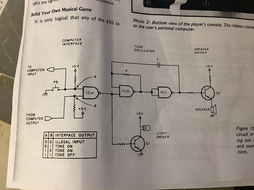
I was looking at making a "Simon" type toy from scratch using an Arduino and other components. I got the idea reading an early Ciarcia's Circuit Cellar circa 1980-81 where he made one of these and was thinking of doing it with more recent components.


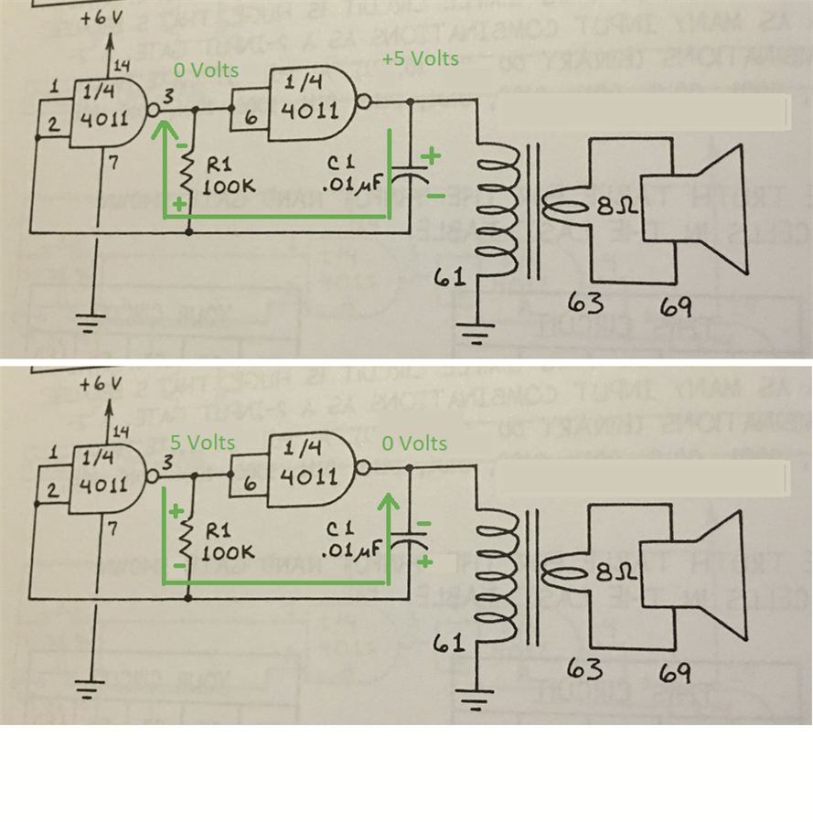
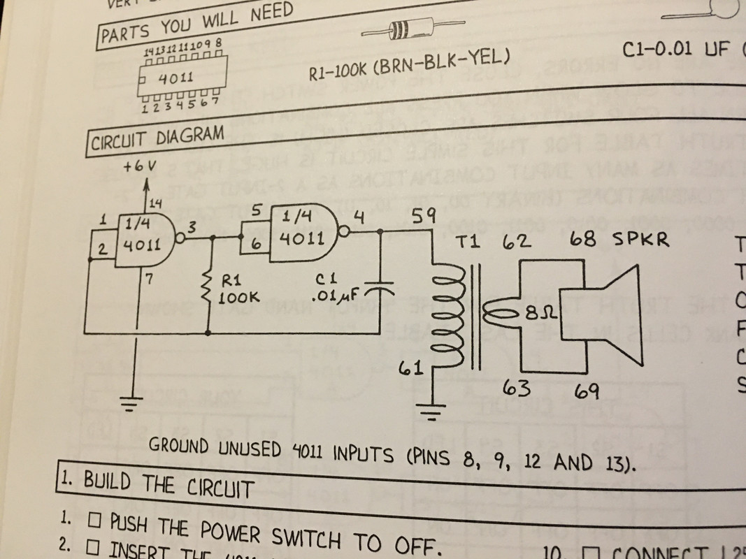
Anyway, in the article he presents a schematic of the hardware tone generator he built for the game and I thought "Cool I can understand this!"... or so I thought lol!  What I am lost on is the charging of the capacitor in the oscillator circuit (below, and then a detailed view below that):

image

image


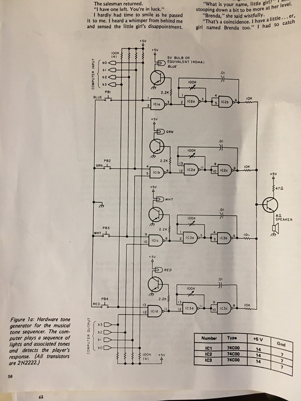
I studied this quite a while and realized I had seen it before in Forrest Mims' Digital Logic Projects:

image

and his explanation:

image


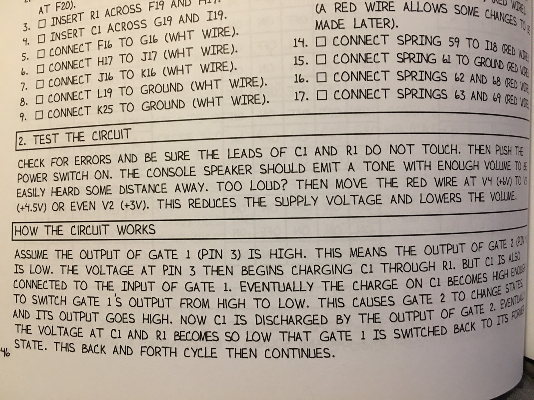
Where I am lost is how C1 (C in Ciarcia's circuit) is charging.  So two questions:


1) I would think the positive side of C1 would be accumulating positive charge, but if pin 4 is low then nothing is going to the positive side of C1?


2) The first answer in this discussion I found of this very circuit says "C1 will get charged through R1.By "charged" i mean lower terminal of C1 will get increasingly positive."  However, the "lower terminal" is the negative polarity side of the capacitor - so how is it accumulating a positive charge? Isn't putting a positive charge on the negative side of a capacitor a Very Bad Thing?


I know I am (again) missing something very basic here!  I have looked at this for 3 days now and not made progress...Thanks for any help on this!

Robert Opalko

  • Sign in to reply
  • Cancel

Top Replies

  • michaelwylie
    michaelwylie over 4 years ago +6 suggested
    The two extremes of the circuit are shown below. For this capacitor, it must be non-polarized, that is, able to hold electrons or holes on either plate. Look at the top circuit, when the output of the…
  • jc2048
    jc2048 over 4 years ago in reply to opalko +5 suggested
    Here are a few examples of capacitor symbols from old books. This is from Troubleshooting Analog circuits by Robert Pease [1991]. The circuit is a simple voltage regulator. He uses a curved plate to denote…
  • gdstew
    gdstew over 4 years ago +4 suggested
    Hi, First these are non-polarized capacitors so they don't have positive or negative terminals. Polarized capacitors like electrolytic and tantalum do have positive and negative terminals and applying…
Parents
  • michaelwylie
    0 michaelwylie over 4 years ago

    The two extremes of the circuit are shown below. For this capacitor, it must be non-polarized, that is, able to hold electrons or holes on either plate. Look at the top circuit, when the output of the leftmost 4011 toggles, the output of the rightmost 4011 will want to go to 0 volts as shown in the bottom picture. Essentially the current flow alternates charging and discharging the capacitor.


    image

    • Cancel
    • Vote Up +6 Vote Down
    • Sign in to reply
    • Verify Answer
    • Reject Answer
    • Cancel
Reply
  • michaelwylie
    0 michaelwylie over 4 years ago

    The two extremes of the circuit are shown below. For this capacitor, it must be non-polarized, that is, able to hold electrons or holes on either plate. Look at the top circuit, when the output of the leftmost 4011 toggles, the output of the rightmost 4011 will want to go to 0 volts as shown in the bottom picture. Essentially the current flow alternates charging and discharging the capacitor.


    image

    • Cancel
    • Vote Up +6 Vote Down
    • Sign in to reply
    • Verify Answer
    • Reject Answer
    • Cancel
Children
No Data
element14 Community

element14 is the first online community specifically for engineers. Connect with your peers and get expert answers to your questions.

  • Members
  • Learn
  • Technologies
  • Challenges & Projects
  • Products
  • Store
  • About Us
  • Feedback & Support
  • FAQs
  • Terms of Use
  • Privacy Policy
  • Legal and Copyright Notices
  • Sitemap
  • Cookies

An Avnet Company © 2025 Premier Farnell Limited. All Rights Reserved.

Premier Farnell Ltd, registered in England and Wales (no 00876412), registered office: Farnell House, Forge Lane, Leeds LS12 2NE.

ICP 备案号 10220084.

Follow element14

  • X
  • Facebook
  • linkedin
  • YouTube