Hi!
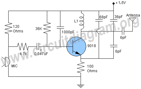
How exactly does an FM transmitter work?
What does every single component do in the process?
Please explane in detale..
Be sure to click 'more' and select 'suggest as answer'!
If you're the thread creator, be sure to click 'more' then 'Verify as Answer'!
Hi Magnus,
FM (frequency modulation) simply means the transmitter output frequency is proportional to the amplitude of the input (modulating) signal.
The larger or louder the input signal the higher the transmitter frequency. The amplitude of the transmitted signal is constant - only its frequency changes.
There is a large amount of information on the internet about FM if you need real detail:
What is FM | Frequency Modulation Tutorial | Radio-Electronics.com
There are three basic ways to modulate information onto a signal. Look at the basic equation for a sine wave:
A(f,t) = Amplitude * sin(2*pi*frequency + phase)
You can either change the amplitude, frequency, phase, or any combination there of. If you change the frequency in proportion to your signal of interest, then it's called frequency modulation.
Edit: There are many FM modulation circuits. If you would like to post one, I'm sure we could decipher it for you.
I'm not sure how much you know, but the basic circuit you have shown is an oscillator where the oscillator frequency can be slightly modified by the microphone. The values of L and that 36 pF capacitor are creating a tank circuit which defines the carrier frequency. Do you need more than this?
Just a picayune clarification, which will probably obfuscate, while you can modulate phase, frequency and amplitude, they are not totally decoupled. Fourier analysis would show that modulating AM has an FM implication in that the instantaneous-rate-of-change changes, and vice-verse. Even AM stations need channel (frequency) spacing, based upon their modulation index. I think that FM and phase modulation look sorta similar instantaneously, as well, IIRC.
Another thought I had, I think this configuration is a Colpitts oscillator. You could possibly look that up for more information.
These little oscillators are nifty to demo RF, but they aren't as stable as modern designs that use PLL or DDS, which use, typically, a crystal for their reference, unless they are thermally stabilized and stuff. Spectral purity can also be an issue with the simplest jobs.
In the states, ham licenses aren't too hard to acquire, these days.
I remember building a transmitter like this one in school and the demodulator as well. We transmitted Metallica across the lab with success and the sound was pretty good too.
Sure, spectral purity isn't going to be an issue in transmitting information in FM, because the detector saturates. It is unintended transmission that concerns me here. If we keep our output power down, we are good. I live in one of the most crowded areas of the US, every broadcast slot is taken. NEIU WZRD* is only allowed 1KW, bleeds into Kennedy/King down by the loop, won't get past Cucumberland on the tollway, I digress. I've found a little post-filtration very helpful with these, just sayin'
FM was introduced during WWII and was quite welcome for its quality. It did not displace AM entirely for servicemen in the field. Our soldiers found that when it (FM) reached the geographical edge if faded precipitantly, 'cause the AGC gave out. AM got progressively noisier when it reached the edge, due to the linear nature of the RF front-end. This typically gave our boys much more time to agree to increase power or alter their relay scheme.
And yeah, we are in agreement, because it is a demo app to which you refer!
Not saying that these radios aren't great fun, just QRP and for the country.
-----------
*Best station ever! -- now on WWW. How come NW WNUR gets 10KW?