element14 Community
element14 Community
    Register Log In
  • Site
  • Search
  • Log In Register
  • About Us
  • Community Hub
    Community Hub
    • What's New on element14
    • Feedback and Support
    • Benefits of Membership
    • Personal Blogs
    • Members Area
    • Achievement Levels
  • Learn
    Learn
    • Ask an Expert
    • eBooks
    • element14 presents
    • Learning Center
    • Tech Spotlight
    • STEM Academy
    • Webinars, Training and Events
    • Learning Groups
  • Technologies
    Technologies
    • 3D Printing
    • FPGA
    • Industrial Automation
    • Internet of Things
    • Power & Energy
    • Sensors
    • Technology Groups
  • Challenges & Projects
    Challenges & Projects
    • Design Challenges
    • element14 presents Projects
    • Project14
    • Arduino Projects
    • Raspberry Pi Projects
    • Project Groups
  • Products
    Products
    • Arduino
    • Avnet Boards Community
    • Dev Tools
    • Manufacturers
    • Multicomp Pro
    • Product Groups
    • Raspberry Pi
    • RoadTests & Reviews
  • Store
    Store
    • Visit Your Store
    • Choose another store...
      • Europe
      •  Austria (German)
      •  Belgium (Dutch, French)
      •  Bulgaria (Bulgarian)
      •  Czech Republic (Czech)
      •  Denmark (Danish)
      •  Estonia (Estonian)
      •  Finland (Finnish)
      •  France (French)
      •  Germany (German)
      •  Hungary (Hungarian)
      •  Ireland
      •  Israel
      •  Italy (Italian)
      •  Latvia (Latvian)
      •  
      •  Lithuania (Lithuanian)
      •  Netherlands (Dutch)
      •  Norway (Norwegian)
      •  Poland (Polish)
      •  Portugal (Portuguese)
      •  Romania (Romanian)
      •  Russia (Russian)
      •  Slovakia (Slovak)
      •  Slovenia (Slovenian)
      •  Spain (Spanish)
      •  Sweden (Swedish)
      •  Switzerland(German, French)
      •  Turkey (Turkish)
      •  United Kingdom
      • Asia Pacific
      •  Australia
      •  China
      •  Hong Kong
      •  India
      •  Korea (Korean)
      •  Malaysia
      •  New Zealand
      •  Philippines
      •  Singapore
      •  Taiwan
      •  Thailand (Thai)
      • Americas
      •  Brazil (Portuguese)
      •  Canada
      •  Mexico (Spanish)
      •  United States
      Can't find the country/region you're looking for? Visit our export site or find a local distributor.
  • Translate
  • Profile
  • Settings
Experts, Learning and Guidance
  • Technologies
  • More
Experts, Learning and Guidance
Ask an Expert Forum For FET-sake, I keep switching and cannot find a suitable MOSFET (or BJT)
  • Blog
  • Forum
  • Documents
  • Leaderboard
  • Files
  • Members
  • Mentions
  • Sub-Groups
  • Tags
  • More
  • Cancel
  • New
Join Experts, Learning and Guidance to participate - click to join for free!
Actions
  • Share
  • More
  • Cancel
Forum Thread Details
  • State Suggested Answer
  • Replies 33 replies
  • Answers 12 answers
  • Subscribers 287 subscribers
  • Views 7078 views
  • Users 0 members are here
  • mosfet relay
  • transistor switch
Related
See a helpful answer?

Be sure to click 'more' and select 'suggest as answer'!

If you're the thread creator, be sure to click 'more' then 'Verify as Answer'!

For FET-sake, I keep switching and cannot find a suitable MOSFET (or BJT)

BigG
BigG over 3 years ago

I came across this lovely term on Twitter the other day for tablet and laptop battery packs that had seen better days (usually when continuously powered/charged). It's #spicy pillow. LOL.


https://twitter.com/hashtag/spicypillow?lang=en


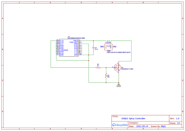
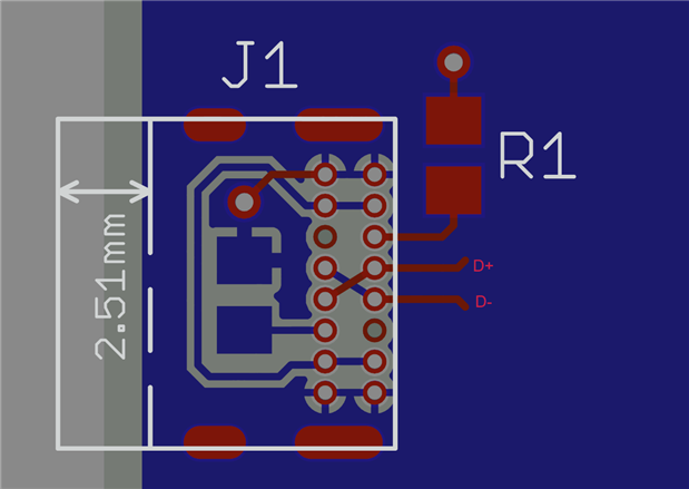
Anyway, this reminded me of a little project I had in mind (as shown in schema below).


image

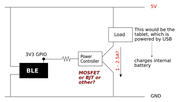
As a electronics novice, this appears to be a borderline case as I know that transistors tend to work well for mA switches while MOSFETs tend to be targeted at higher voltages (and say +3A current).


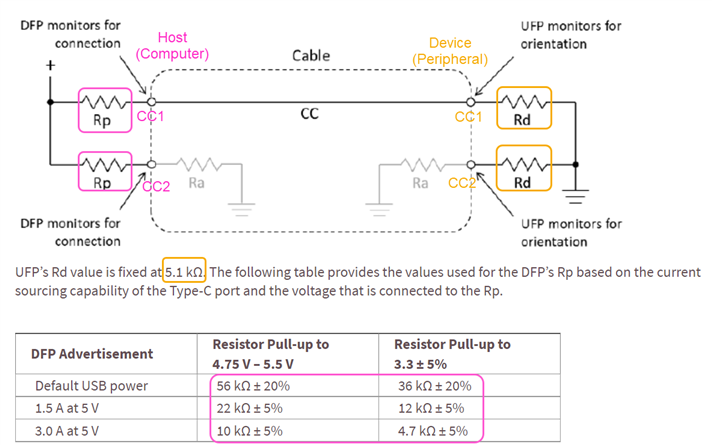
So now struggling to choose a suitable component - I'm particularly interested at the 1.5A option as that tends to be the limit for many usb charger adapters:


image


Having done some prelim research it looks like FET's are the way to go but when working through my design criteria I'm quickly getting bogged down in the detail... In this case I'm not coming up with options as I can see that I need to minimise my resistance losses to reduce voltage drop etc... I'm also looking for a low cost <1$ SMD option.


Hence I thought to open this little design challenge to the members as I had to chuckle at aGough Lui status update I found when doing my e14 search...


Often we're lazy, choosing to use the same parts over and over. I'm guilty of this when it comes to...


So, any old favourite FETs you have which could well work here?

  • Sign in to reply
  • Cancel

Top Replies

  • michaelkellett
    michaelkellett over 3 years ago +7 suggested
    Don't have favourites. Always use a part for a reason (usually many reasons). Having a reel of 999 of a part is a good reason if it will work OK ! In your case with 3.3V drive, 5V power supply, a load…
  • colporteur
    colporteur over 3 years ago +3 suggested
    Absolutely loved the title of your post! You have to start writing for British tabloids. I missed the meaning of the hashtag. I have little exposure to the sun or social media from under the bridge I only…
  • BigG
    BigG over 3 years ago in reply to colporteur +3 suggested
    LOL. (British tabloids) I missed the meaning of the hashtag. Batteries look like pillows. As to where "spicy" came from, who knows, so I had to look it up (thanks Google) https://www.urbandictionary.com…
Parents
  • BigG
    0 BigG over 3 years ago

    All thanks to https://oshpark.com/, it cost me about $10 to get 3 boards made up and delivered using their express service. Very impressed.


    image


    As you can see from the above schematic, the board is designed to be attached to a Nordic Semiconductor nRF52840 dongle - these are great low cost dev boards that can be slotted directly into a USB port. The MOSFET I decided to use was partly based on the fact that it was in stock and is low cost.


    https://www.vishay.com/docs/63302/si2342ds.pdf


    It works - I verified manually.


    Now I'm able to control the power to any device attached, using BLE to remotely switch power on and off. Well that's the theory. Now I just need to get my nRF52840 firmware sorted. Fingers crossed.


    {gallery:autoplay=false} USBLE Spicy Controller Board

    image

    The underside of my USBLE spicy controller board

    image

    My USBLE Spicy Controller attached to an nRF52840 dongle

    image

    nRF52840 USB dongle inserted into laptop

    • Cancel
    • Vote Up 0 Vote Down
    • Sign in to reply
    • Verify Answer
    • Reject Answer
    • Cancel
  • shabaz
    0 shabaz over 3 years ago in reply to BigG

    Hi Colin,


    Nice project! One thing you might (or might not) need (can be easily hacked in place hopefully, perhaps with surface mount resistors, is a resistance between the data pins, because the tablet/end device might not draw too much current without it - It's called Dedicated Charging Port (or other options are possible), I don't know the precise details but they should be published, there's some brief information here: SILICON LABS USB-TO-UART Bridge Controller EVM - Review

    (in the 'Battery Charging Negotiation' section)

    • Cancel
    • Vote Up 0 Vote Down
    • Sign in to reply
    • Verify Answer
    • Reject Answer
    • Cancel
  • BigG
    0 BigG over 3 years ago in reply to shabaz

    Yes, I wondered about that. Thankfully it works with my old Android tablets - see video demo.


    You don't have permission to edit metadata of this video.
    Edit media
    x
    image
    Upload Preview
    image


    I have a new Android phone, which uses USB C. I suspect that with this phone I'll need to make a few mods. In particular I'd need a better MOSFET as with fast charge you can draw over 2 Amps. Not sure what else will be needed for USB-C regarding data lines. Needs further research.


    EDIT... ah! I see what you mean.


    I've just done some further testing and whilst it (sort of) works I can see that the current draw does differ depending on device and whether it is charged by laptop or otherwise.


    TEST 1: Charging tablet (Amazon FIRE 7) directly from laptop. Here the current draw is less than shown in the video demo.

    image


    TEST 2: Charging tablet directly from a USB charger. Here the current draw is higher.


    image


    TEST 3: Attaching the USBLE Spicy Controller to USB charger. Here the current draw is less and is similar to the current draw when charging directly from a laptop.

    image

    • Cancel
    • Vote Up 0 Vote Down
    • Sign in to reply
    • Verify Answer
    • Cancel
  • shabaz
    0 shabaz over 3 years ago in reply to BigG

    Hi Colin,


    I'm in the same situation, many devices with USB-C, so I ordered some connectors - they arrived today - so that I can in future lay out boards with that rather than (in my case for USB peripheral) Micro-USB. From what I read, since the connector works in both orientations, the data pins are replicated so they need to be connected together, and then there is a pin called CC, again replicated, and each of those separately needs to be connected via a resistor, to 0V or to the supply. The computer end (host) connects it high, and the peripheral end (device) connects it low. The diagram below was from a Cypress document but I found it hard to follow so I put some colour-coded annotations on it below.


    image


    Personally I went with this USB-C connectorthis USB-C connector which is through-hole (I preferred SMD but I didn't see one that looked easy to solder). The through-hole won't be particularly easy to solder either, since the pins are extremely close, but that's life - I've bought enough to last me a while! so I have to go with what I have.

    • Cancel
    • Vote Up 0 Vote Down
    • Sign in to reply
    • Verify Answer
    • Reject Answer
    • Cancel
Reply
  • shabaz
    0 shabaz over 3 years ago in reply to BigG

    Hi Colin,


    I'm in the same situation, many devices with USB-C, so I ordered some connectors - they arrived today - so that I can in future lay out boards with that rather than (in my case for USB peripheral) Micro-USB. From what I read, since the connector works in both orientations, the data pins are replicated so they need to be connected together, and then there is a pin called CC, again replicated, and each of those separately needs to be connected via a resistor, to 0V or to the supply. The computer end (host) connects it high, and the peripheral end (device) connects it low. The diagram below was from a Cypress document but I found it hard to follow so I put some colour-coded annotations on it below.


    image


    Personally I went with this USB-C connectorthis USB-C connector which is through-hole (I preferred SMD but I didn't see one that looked easy to solder). The through-hole won't be particularly easy to solder either, since the pins are extremely close, but that's life - I've bought enough to last me a while! so I have to go with what I have.

    • Cancel
    • Vote Up 0 Vote Down
    • Sign in to reply
    • Verify Answer
    • Reject Answer
    • Cancel
Children
  • fmilburn
    0 fmilburn over 3 years ago in reply to shabaz

    Hi Shabaz,

    That does look like it could be difficult to solder. Some of the less expensive PCB manufacturers may not be able to put solder mask between the pads. I would be interested in your experience as this is something I would like to try.

    • Cancel
    • Vote Up 0 Vote Down
    • Sign in to reply
    • Verify Answer
    • Cancel
  • shabaz
    0 shabaz over 3 years ago in reply to fmilburn

    Hi Frank,


    You're right, it's very likely solder mask will break in the blue regions here. The spacing between the rows is a bit more, so hopefully if the iron and solder are applied as shown with the red and orange arrows, then hopefully it's doable.. it's really tight though, the pitch is 0.85mm between pins within the same row.

    image


    I gave the layout a shot, that is more complicated than Micro-USB since the two resistors are needed, but it is not too bad provided at least one resistor is on the underside of the board, otherwise it's a lot more awkward. These resistors are 0805 sized in the screenshot below. I might tweak this a bit more, but I think broadly I'm going with this sort of layout.

    image

    • Cancel
    • Vote Up +1 Vote Down
    • Sign in to reply
    • Verify Answer
    • Reject Answer
    • Cancel
  • michaelkellett
    0 michaelkellett over 3 years ago in reply to shabaz

    If it were me I'd be quite happy with surface mount.


    Farnell have 3019726 which is Hirose CX90-M, it has the connector pins on a 0.5mm pitch, same as a typical surface mount uP.


    No problem at all to hand solder if you use flux and a sensible iron.


    And a piece of cake if you silk screen and reflow.


    The SM connectors cost more image


    MK

    • Cancel
    • Vote Up 0 Vote Down
    • Sign in to reply
    • Verify Answer
    • Cancel
  • shabaz
    0 shabaz over 3 years ago in reply to michaelkellett

    Hi Michael,


    That looks nice, with the surface mount pins not recessed in. Great for hand-soldering. Couple of mm shorter than the through-hole ones too.

    I'll have to make do with the through-hole ones (I bought quite a few) until I get through them all : (

    Incidentally I also obtained a couple of 6-pin USB-C connectors6-pin USB-C connectors that only have the power pins and the CC pins exposed. They are very easy to solder as a result (can even tack on wires to them easily), but I don't think I'll be using them except to perhaps quickly prototype anything charging related.


    Photos below of the USB4085-GF-A through-hole, and the 6-pin USB4125-GF-A :


    image

    image

    • Cancel
    • Vote Up 0 Vote Down
    • Sign in to reply
    • Verify Answer
    • Reject Answer
    • Cancel
  • shabaz
    0 shabaz over 3 years ago in reply to fmilburn

    As an experiment I decided to try the USB-C for a UART adapter. This is using a Cypress chip CY7C65213, I usually use a simpler Microchip part but the Cypress one has more features. I'll write it up as a separate thread at some point, if it functions!

    image

    • Cancel
    • Vote Up 0 Vote Down
    • Sign in to reply
    • Verify Answer
    • Cancel
element14 Community

element14 is the first online community specifically for engineers. Connect with your peers and get expert answers to your questions.

  • Members
  • Learn
  • Technologies
  • Challenges & Projects
  • Products
  • Store
  • About Us
  • Feedback & Support
  • FAQs
  • Terms of Use
  • Privacy Policy
  • Legal and Copyright Notices
  • Sitemap
  • Cookies

An Avnet Company © 2025 Premier Farnell Limited. All Rights Reserved.

Premier Farnell Ltd, registered in England and Wales (no 00876412), registered office: Farnell House, Forge Lane, Leeds LS12 2NE.

ICP 备案号 10220084.

Follow element14

  • X
  • Facebook
  • linkedin
  • YouTube