element14 Community
element14 Community
    Register Log In
  • Site
  • Search
  • Log In Register
  • Community Hub
    Community Hub
    • What's New on element14
    • Feedback and Support
    • Benefits of Membership
    • Personal Blogs
    • Members Area
    • Achievement Levels
  • Learn
    Learn
    • Ask an Expert
    • eBooks
    • element14 presents
    • Learning Center
    • Tech Spotlight
    • STEM Academy
    • Webinars, Training and Events
    • Learning Groups
  • Technologies
    Technologies
    • 3D Printing
    • FPGA
    • Industrial Automation
    • Internet of Things
    • Power & Energy
    • Sensors
    • Technology Groups
  • Challenges & Projects
    Challenges & Projects
    • Design Challenges
    • element14 presents Projects
    • Project14
    • Arduino Projects
    • Raspberry Pi Projects
    • Project Groups
  • Products
    Products
    • Arduino
    • Avnet & Tria Boards Community
    • Dev Tools
    • Manufacturers
    • Multicomp Pro
    • Product Groups
    • Raspberry Pi
    • RoadTests & Reviews
  • About Us
  • Store
    Store
    • Visit Your Store
    • Choose another store...
      • Europe
      •  Austria (German)
      •  Belgium (Dutch, French)
      •  Bulgaria (Bulgarian)
      •  Czech Republic (Czech)
      •  Denmark (Danish)
      •  Estonia (Estonian)
      •  Finland (Finnish)
      •  France (French)
      •  Germany (German)
      •  Hungary (Hungarian)
      •  Ireland
      •  Israel
      •  Italy (Italian)
      •  Latvia (Latvian)
      •  
      •  Lithuania (Lithuanian)
      •  Netherlands (Dutch)
      •  Norway (Norwegian)
      •  Poland (Polish)
      •  Portugal (Portuguese)
      •  Romania (Romanian)
      •  Russia (Russian)
      •  Slovakia (Slovak)
      •  Slovenia (Slovenian)
      •  Spain (Spanish)
      •  Sweden (Swedish)
      •  Switzerland(German, French)
      •  Turkey (Turkish)
      •  United Kingdom
      • Asia Pacific
      •  Australia
      •  China
      •  Hong Kong
      •  India
      • Japan
      •  Korea (Korean)
      •  Malaysia
      •  New Zealand
      •  Philippines
      •  Singapore
      •  Taiwan
      •  Thailand (Thai)
      • Vietnam
      • Americas
      •  Brazil (Portuguese)
      •  Canada
      •  Mexico (Spanish)
      •  United States
      Can't find the country/region you're looking for? Visit our export site or find a local distributor.
  • Translate
  • Profile
  • Settings
Experts, Learning and Guidance
  • Technologies
  • More
Experts, Learning and Guidance
Ask an Expert Forum replacement for a NDP6020P. They stopped making them. How do you find an alternative?
  • Blog
  • Forum
  • Documents
  • Leaderboard
  • Files
  • Members
  • Mentions
  • Sub-Groups
  • Tags
  • More
  • Cancel
  • New
Join Experts, Learning and Guidance to participate - click to join for free!
Actions
  • Share
  • More
  • Cancel
Forum Thread Details
  • State Verified Answer
  • Replies 19 replies
  • Subscribers 302 subscribers
  • Views 5582 views
  • Users 0 members are here
Related
See a helpful answer?

Be sure to click 'more' and select 'suggest as answer'!

If you're the thread creator, be sure to click 'more' then 'Verify as Answer'!

replacement for a NDP6020P. They stopped making them. How do you find an alternative?

madbowman
madbowman over 3 years ago

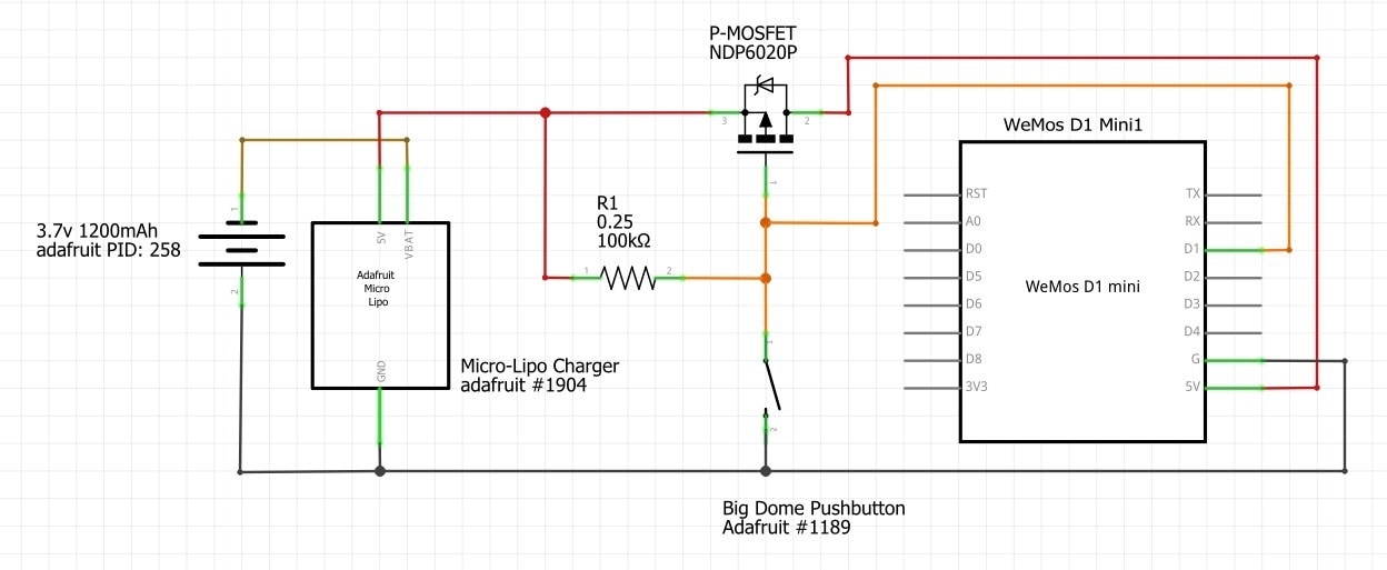
I needed a replacement for a NDP6020P. They stopped making them. How do you find an alternative? They show a dmg3415u as an alternative but that is surface mount only. I think this is one of the hardest parts of electronics.Any help would be awesome. i called a supply company and they said there isn't a replacement for this part. That can't be right. so i bought some no name knock offs, but that doesn't change the fact that i don't know how to find replacements or read data sheets to find the right part. this would make a very useful video i think.

  • Sign in to reply
  • Cancel

Top Replies

  • dougw
    dougw over 3 years ago +2 verified
    It seems the part is obsolete and Newark doesn't carry it anymore, but there are other places that seem to have stock. https://www.solarbotics.com/product/17174?countrycurrency=CA&gclid=EAIaIQobChMIz9HRsN2j9wIVIWxvBB2XVgM3EAQYAiABEgLTtvD_BwE…
  • madbowman
    madbowman over 3 years ago in reply to shabaz +2
    this is what I'm doing. It needs to have a button large enough for a service dog to press and require as little charging as possible. This should shut off 10-15 seconds after pressing. It sends a message…
  • dougw
    dougw over 3 years ago in reply to madbowman +2
    This circuit doesn't appear to need a big FET, almost any P-FET with a low gate threshold would work, although a low on-resistance is always nice.
Parents
  • shabaz
    0 shabaz over 3 years ago

    Hi,

    You might want to share the circuit that you plan to use this device with. It's up to you if you wish to do so, but if it is a hobby circuit from the Internet, it may well not be ideal (there can be better ways to achieve things). RIght now I don't know either way, maybe it actually is the perfect ideal part, but I have no idea, and just from being an overly suspicious person usually!, I'd be wanting to examine the circuit if it were me.

    • Cancel
    • Vote Up +1 Vote Down
    • Sign in to reply
    • Verify Answer
    • Cancel
  • madbowman
    0 madbowman over 3 years ago in reply to shabaz

    this is what I'm doing. It needs to have a button large enough for a service dog to press and require as little charging as possible. This should shut off 10-15 seconds after pressing. It sends a message to home assistant for emergency alerts. I am very new to electronics (less then a year). so I don't know if this will work till breadboard.

    image

    • Cancel
    • Vote Up +2 Vote Down
    • Sign in to reply
    • Verify Answer
    • Cancel
  • madbowman
    0 madbowman over 3 years ago in reply to shabaz

    Good point. The wemos board will be inside a case. so no one will be able to connect the wemos usb into anything. But now I wonder if the 1904 will do the job. You are right a lot more thinking. The bat only has 3.7v and min power for the wemos is 3.3. that might be to close. Maybe I need a 9v and convert it to 5v. then just change it every year. I just hate to waist.

    • Cancel
    • Vote Up 0 Vote Down
    • Sign in to reply
    • Verify Answer
    • Cancel
  • madbowman
    0 madbowman over 3 years ago in reply to shabaz

    I don't think cutting the trace on the board and patching in a pin is something I can do. But I do get what your doing. The wemo will be inside a case and I'm the user. well me and the dog are so that shouldn't be problem, but I think I might be short on power after reading your last post. bat is 3.7 and min for wemos is 3.3. I think i have to rethink a few things.

    • Cancel
    • Vote Up 0 Vote Down
    • Sign in to reply
    • Verify Answer
    • Cancel
  • madbowman
    0 madbowman over 3 years ago in reply to madbowman

    Ok now i get what "add an NPN/NFET in parallel with the pushbutton" from Scottiebabe means. very clever I would have never thought of that.

    • Cancel
    • Vote Up 0 Vote Down
    • Sign in to reply
    • Verify Answer
    • Cancel
  • shabaz
    0 shabaz over 3 years ago in reply to madbowman

    Three AA cells would get you to around 4-4.5V, which if connected to VUSB (i.e. if you are certain no-one will plug in the USB connector while the AA cells are connected) would easily last a year or longer, there's no need for the LiPo charger then.

    If the AA cell holder was mounted in front of the USB port, i.e. you have to physically disconnect the AA cell holder to move it out of the way to plug in the USB connector, then that would solve the problem.

    I recently did something kind of similar, where I just stuck a microswitch with lever, in front of a USB port. The lever is physically in the way of the USB port. The user cannot plug in a USB plug, without pushing down on the microswitch first. The microswitch cuts the power from the battery.

    image

    Kind of an ugly solution, but it solved the problem.

    • Cancel
    • Vote Up +1 Vote Down
    • Sign in to reply
    • Verify Answer
    • Cancel
  • shabaz
    0 shabaz over 3 years ago in reply to madbowman

    You can apply anything from about 3.4V upward to the VUSB pin (i.e. the pin labelled 5V on your diagram) on the Wemos board, it will regulate it down to 3.3V, so three AA cells will do the job (provided you're sure the USB connector won't be plugged in while the AA cells are connected).

    • Cancel
    • Vote Up 0 Vote Down
    • Sign in to reply
    • Verify Answer
    • Cancel
  • scottiebabe
    0 scottiebabe over 3 years ago in reply to madbowman

    I think your doing a great job and working on a really neat project! Your line of thinking is totally correct. After the MCU sets D1 high and turns itself off there are some protection diodes in the chip that may not allow for D1 pin to get pulled up to vbat.

     image

    So, the mcu may never get fully turned off. The schematic shabaz sketched out, shows the additional NPN. This way for the MCU to turn itself off, its sets D1 Low, which is also an allowable IO pin voltage when the power is removed.  

    • Cancel
    • Vote Up +2 Vote Down
    • Sign in to reply
    • Verify Answer
    • Cancel
  • madbowman
    0 madbowman over 3 years ago in reply to scottiebabe

    I cant wait for the parts to get here so i can breadboard this. I want to try it both ways and see what happens. I will let everyone know. In the mean time I need to learn how to pick the right parts. like if I designed this myself how would I know what mosfet and npn to pick.

    • Cancel
    • Vote Up 0 Vote Down
    • Sign in to reply
    • Verify Answer
    • Cancel
  • dougw
    0 dougw over 3 years ago in reply to madbowman

    FET:

    choose a voltage range - anything over 6 V for you, which is any FET

    choose a gate threshold voltage - anything less than 3V  for you

    choose a max current - anything over 100 mA for you, which is pretty much any FET

    choose a package - TO92 for though hole TP2104N3-G  , SOT23 for SMT BSS306NH6327XTSA1

    You may need to limit the voltage going to D1

    • Cancel
    • Vote Up +1 Vote Down
    • Sign in to reply
    • Verify Answer
    • Cancel
  • madbowman
    0 madbowman over 3 years ago in reply to dougw

    ok i tried to add the npn in parallel with the switch but i couldn't get it to work. so i went back to my original schematic and added a tp4056. i haven't tested the bat yet but at least i can get it to work, now. I kind of feel like i failed because i couldn't get the npn to work

    • Cancel
    • Vote Up 0 Vote Down
    • Sign in to reply
    • Verify Answer
    • Cancel
  • madbowman
    0 madbowman over 3 years ago in reply to madbowman

    well that went up in flames. i will be starting over. but now i have to add sound and leds..

    • Cancel
    • Vote Up 0 Vote Down
    • Sign in to reply
    • Verify Answer
    • Cancel
Reply
  • madbowman
    0 madbowman over 3 years ago in reply to madbowman

    well that went up in flames. i will be starting over. but now i have to add sound and leds..

    • Cancel
    • Vote Up 0 Vote Down
    • Sign in to reply
    • Verify Answer
    • Cancel
Children
No Data
element14 Community

element14 is the first online community specifically for engineers. Connect with your peers and get expert answers to your questions.

  • Members
  • Learn
  • Technologies
  • Challenges & Projects
  • Products
  • Store
  • About Us
  • Feedback & Support
  • FAQs
  • Terms of Use
  • Privacy Policy
  • Legal and Copyright Notices
  • Sitemap
  • Cookies

An Avnet Company © 2026 Premier Farnell Limited. All Rights Reserved.

Premier Farnell Ltd, registered in England and Wales (no 00876412), registered office: Farnell House, Forge Lane, Leeds LS12 2NE.

ICP 备案号 10220084.

Follow element14

  • X
  • Facebook
  • linkedin
  • YouTube