element14 Community
element14 Community
    Register Log In
  • Site
  • Search
  • Log In Register
  • Community Hub
    Community Hub
    • What's New on element14
    • Feedback and Support
    • Benefits of Membership
    • Personal Blogs
    • Members Area
    • Achievement Levels
  • Learn
    Learn
    • Ask an Expert
    • eBooks
    • element14 presents
    • Learning Center
    • Tech Spotlight
    • STEM Academy
    • Webinars, Training and Events
    • Learning Groups
  • Technologies
    Technologies
    • 3D Printing
    • FPGA
    • Industrial Automation
    • Internet of Things
    • Power & Energy
    • Sensors
    • Technology Groups
  • Challenges & Projects
    Challenges & Projects
    • Design Challenges
    • element14 presents Projects
    • Project14
    • Arduino Projects
    • Raspberry Pi Projects
    • Project Groups
  • Products
    Products
    • Arduino
    • Avnet & Tria Boards Community
    • Dev Tools
    • Manufacturers
    • Multicomp Pro
    • Product Groups
    • Raspberry Pi
    • RoadTests & Reviews
  • About Us
  • Store
    Store
    • Visit Your Store
    • Choose another store...
      • Europe
      •  Austria (German)
      •  Belgium (Dutch, French)
      •  Bulgaria (Bulgarian)
      •  Czech Republic (Czech)
      •  Denmark (Danish)
      •  Estonia (Estonian)
      •  Finland (Finnish)
      •  France (French)
      •  Germany (German)
      •  Hungary (Hungarian)
      •  Ireland
      •  Israel
      •  Italy (Italian)
      •  Latvia (Latvian)
      •  
      •  Lithuania (Lithuanian)
      •  Netherlands (Dutch)
      •  Norway (Norwegian)
      •  Poland (Polish)
      •  Portugal (Portuguese)
      •  Romania (Romanian)
      •  Russia (Russian)
      •  Slovakia (Slovak)
      •  Slovenia (Slovenian)
      •  Spain (Spanish)
      •  Sweden (Swedish)
      •  Switzerland(German, French)
      •  Turkey (Turkish)
      •  United Kingdom
      • Asia Pacific
      •  Australia
      •  China
      •  Hong Kong
      •  India
      • Japan
      •  Korea (Korean)
      •  Malaysia
      •  New Zealand
      •  Philippines
      •  Singapore
      •  Taiwan
      •  Thailand (Thai)
      • Vietnam
      • Americas
      •  Brazil (Portuguese)
      •  Canada
      •  Mexico (Spanish)
      •  United States
      Can't find the country/region you're looking for? Visit our export site or find a local distributor.
  • Translate
  • Profile
  • Settings
Experts, Learning and Guidance
  • Technologies
  • More
Experts, Learning and Guidance
Ask an Expert Forum What is the minimum range in millivolts in a linear optocoupler
  • Blog
  • Forum
  • Documents
  • Leaderboard
  • Files
  • Members
  • Mentions
  • Sub-Groups
  • Tags
  • More
  • Cancel
  • New
Join Experts, Learning and Guidance to participate - click to join for free!
Actions
  • Share
  • More
  • Cancel
Forum Thread Details
  • State Not Answered
  • Replies 6 replies
  • Subscribers 303 subscribers
  • Views 2038 views
  • Users 0 members are here
  • linear optocoupler
Related
See a helpful answer?

Be sure to click 'more' and select 'suggest as answer'!

If you're the thread creator, be sure to click 'more' then 'Verify as Answer'!

What is the minimum range in millivolts in a linear optocoupler

A3JBNE
A3JBNE over 3 years ago

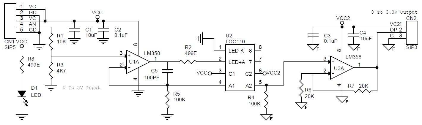
I would like to know how many minimum millivolts can pass through the optocoupler, for example in a working range of 1mv to 10mV (input output) will there be problems in its operation?

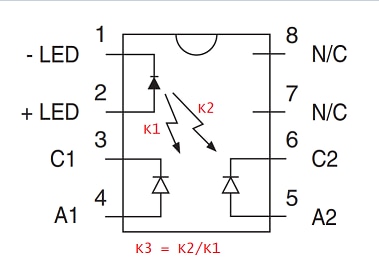
Where in the LOC110 linear optocoupler data sheet is it specified?

image

  • Sign in to reply
  • Cancel

Top Replies

  • scottiebabe
    scottiebabe over 3 years ago in reply to A3JBNE +2
    The 1mA to 10mA LED current rating is where the servo-linearity is guaranteed. The LED and photodiodes/transistors are absolutely still going to work on lower photos currents. I just can't say how well…
  • A3JBNE
    A3JBNE over 3 years ago in reply to scottiebabe +1
    In a simulation R5 and R4 have a maximum current of 22 uA for a transfer of 2.5V, R2 = 499omhs, R5 and R4 = 100K. So 22uA is nowhere near 1mA
  • scottiebabe
    scottiebabe over 3 years ago in reply to A3JBNE +1
    Sounds reasonable enough, the CTR from LED to photodiode is quite low, K1 & K2 are specified as typically 0.007 A/A 22 uA is a little on the low end where the part has been characterized for closed…
  • dougw
    0 dougw over 3 years ago

    The input-to-output ratio is specified as a current transfer ratio - "Transfer Gain" (K3). Nominally it is about 1. If you want it to be accurate, you will likely need to calibrate it.

    • Cancel
    • Vote Up 0 Vote Down
    • Sign in to reply
    • Verify Answer
    • Cancel
  • scottiebabe
    0 scottiebabe over 3 years ago

    In case you missed it I would recommend you skim through: https://www.ixysic.com/home/pdfs.nsf/www/AN-107.pdf/$file/AN-107.pdf 

    The optocoupler operates based on photocurrent. So in you would selected R1 & R2 such that the LED current is in it recommended operating range of 1 to 10 mA. Selecting the right op-amps is going to be a major performance factor operating at just 1 mV to 10 mV above the ground rail.

    • Cancel
    • Vote Up 0 Vote Down
    • Sign in to reply
    • Verify Answer
    • Cancel
  • A3JBNE
    0 A3JBNE over 3 years ago in reply to scottiebabe

    In a simulation R5 and R4 have a maximum current of 22 uA for a transfer of 2.5V, R2 = 499omhs, R5 and R4 = 100K.
    So 22uA is nowhere near 1mA  

    image

    • Cancel
    • Vote Up +1 Vote Down
    • Sign in to reply
    • Verify Answer
    • Cancel
  • scottiebabe
    0 scottiebabe over 3 years ago in reply to A3JBNE

    Sounds reasonable enough, the CTR from LED to photodiode is quite low, K1 & K2 are specified as typically 0.007 A/A

    image

    22 uA is a little on the low end where the part has been characterized for closed loop servo linearity:

    image 

    • Cancel
    • Vote Up +1 Vote Down
    • Sign in to reply
    • Verify Answer
    • Cancel
  • A3JBNE
    0 A3JBNE over 3 years ago in reply to scottiebabe

    So the operating range of the LED is from 1mA to 10mA, I have an input signal of "0 to 2.5V", so I have to scale from "1V to 2.5V" so that 1V is the minimum voltage it will give me the minimum current 1mA approximately and 2.5V the maximum current. To adjust the minimum current I will have to calculate the resistor referring to K1 until I obtain 1mA of LED current for 1V input.


    Because in the schematic example it uses a "0 to 2V" input signal. It is assumed that 0V is equal to 0mA for the LED.

    What if I use different voltages for VCC1=5V and VCC2=18V will it affect the K3 gain?

    image

    • Cancel
    • Vote Up 0 Vote Down
    • Sign in to reply
    • Verify Answer
    • Cancel
  • scottiebabe
    0 scottiebabe over 3 years ago in reply to A3JBNE

    The 1mA to 10mA LED current rating is where the servo-linearity is guaranteed. The LED and photodiodes/transistors are absolutely still going to work on lower photos currents. I just can't say how well, if you built this on a breadboard I'm sure it would work just fine (though vout will be 0-2V for R1=R2).

    Surprisingly the datasheet doesn't list a voltage rating for the photodiodes/transistor so I can only assume 18V is okay...

    • Cancel
    • Vote Up +2 Vote Down
    • Sign in to reply
    • Verify Answer
    • Cancel
element14 Community

element14 is the first online community specifically for engineers. Connect with your peers and get expert answers to your questions.

  • Members
  • Learn
  • Technologies
  • Challenges & Projects
  • Products
  • Store
  • About Us
  • Feedback & Support
  • FAQs
  • Terms of Use
  • Privacy Policy
  • Legal and Copyright Notices
  • Sitemap
  • Cookies

An Avnet Company © 2025 Premier Farnell Limited. All Rights Reserved.

Premier Farnell Ltd, registered in England and Wales (no 00876412), registered office: Farnell House, Forge Lane, Leeds LS12 2NE.

ICP 备案号 10220084.

Follow element14

  • X
  • Facebook
  • linkedin
  • YouTube