element14 Community
element14 Community
    Register Log In
  • Site
  • Search
  • Log In Register
  • Community Hub
    Community Hub
    • What's New on element14
    • Feedback and Support
    • Benefits of Membership
    • Personal Blogs
    • Members Area
    • Achievement Levels
  • Learn
    Learn
    • Ask an Expert
    • eBooks
    • element14 presents
    • Learning Center
    • Tech Spotlight
    • STEM Academy
    • Webinars, Training and Events
    • Learning Groups
  • Technologies
    Technologies
    • 3D Printing
    • FPGA
    • Industrial Automation
    • Internet of Things
    • Power & Energy
    • Sensors
    • Technology Groups
  • Challenges & Projects
    Challenges & Projects
    • Design Challenges
    • element14 presents Projects
    • Project14
    • Arduino Projects
    • Raspberry Pi Projects
    • Project Groups
  • Products
    Products
    • Arduino
    • Avnet Boards Community
    • Dev Tools
    • Manufacturers
    • Multicomp Pro
    • Product Groups
    • Raspberry Pi
    • RoadTests & Reviews
  • About Us
  • Store
    Store
    • Visit Your Store
    • Choose another store...
      • Europe
      •  Austria (German)
      •  Belgium (Dutch, French)
      •  Bulgaria (Bulgarian)
      •  Czech Republic (Czech)
      •  Denmark (Danish)
      •  Estonia (Estonian)
      •  Finland (Finnish)
      •  France (French)
      •  Germany (German)
      •  Hungary (Hungarian)
      •  Ireland
      •  Israel
      •  Italy (Italian)
      •  Latvia (Latvian)
      •  
      •  Lithuania (Lithuanian)
      •  Netherlands (Dutch)
      •  Norway (Norwegian)
      •  Poland (Polish)
      •  Portugal (Portuguese)
      •  Romania (Romanian)
      •  Russia (Russian)
      •  Slovakia (Slovak)
      •  Slovenia (Slovenian)
      •  Spain (Spanish)
      •  Sweden (Swedish)
      •  Switzerland(German, French)
      •  Turkey (Turkish)
      •  United Kingdom
      • Asia Pacific
      •  Australia
      •  China
      •  Hong Kong
      •  India
      •  Korea (Korean)
      •  Malaysia
      •  New Zealand
      •  Philippines
      •  Singapore
      •  Taiwan
      •  Thailand (Thai)
      • Americas
      •  Brazil (Portuguese)
      •  Canada
      •  Mexico (Spanish)
      •  United States
      Can't find the country/region you're looking for? Visit our export site or find a local distributor.
  • Translate
  • Profile
  • Settings
Experts, Learning and Guidance
  • Technologies
  • More
Experts, Learning and Guidance
Ask an Expert Forum Emulating keypad signals to microcontroller?
  • Blog
  • Forum
  • Documents
  • Leaderboard
  • Files
  • Members
  • Mentions
  • Sub-Groups
  • Tags
  • More
  • Cancel
  • New
Join Experts, Learning and Guidance to participate - click to join for free!
Actions
  • Share
  • More
  • Cancel
Forum Thread Details
  • State Not Answered
  • Replies 7 replies
  • Subscribers 293 subscribers
  • Views 1969 views
  • Users 0 members are here
  • multiplexer
  • microcontroller
  • arduino
Related
See a helpful answer?

Be sure to click 'more' and select 'suggest as answer'!

If you're the thread creator, be sure to click 'more' then 'Verify as Answer'!

Emulating keypad signals to microcontroller?

opalko
opalko over 3 years ago

Hey folks, I always learn so much here. I am back with another question:
About a year ago in one of my retro computing buying binges, I purchased a Science Fair (Radio Shack) Microcomputer Trainer..these are circa 1985.

http://oldcomputermuseum.com/microcomputer_trainer.html

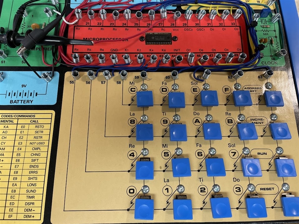
The SFMT has a keypad of simple switches.

image

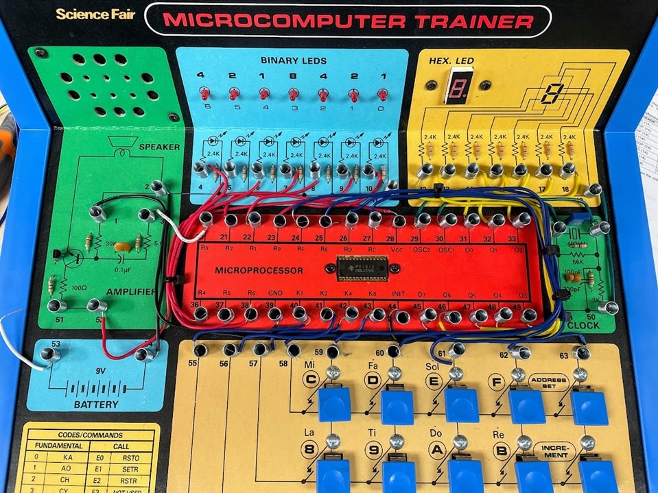
Program instructions in assembly language are entered via the switches. The heart of the unit is a Texas Instruments CMP1312.  It is a flashed version of their TMS-1100 microcrontroller which is a subset of the TMS-1000:

https://www.seanriddle.com/datasheets/ti/TMS1000pgmRef_1975.pdf

The CMP1312 is a flashed version of the TMS1100 for use exclusively in the SFMT. It has several programs and games built into it, but you can write your own programs with it as well.

There are 5 columns of switches which are attached to pins O7, Rc-Rf on the CMP1312 microcontroller on the SFMT.
These channels are strobed. The 4 rows of keys are attached to channels/lines K1, K2, K4, K8 are at system ground until a key is pressed.

image

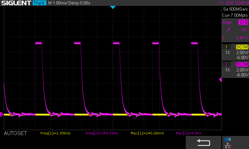
As I think I understand it when a key column is strobed the CMP1312 is looking to see if there is a keypress on that column. A circuit between the K-lines and R-lines is closed when a key is pressed and the CMP1312 registers as an instruction.  Here is a scope shot of the pulsing of one of the R lines. The yellow line is one of the K lines and at 0V:

image

It is not really fun to enter programs of any length via the keypad interface. For one thing they aren't laid out in a traditional telephone/calculator keypad arrangement. This makes it difficult to fight the impulse to look for a "7" in the upper left corner - it is on the lower right...etc. Also there is no way to store programs if you wanted to. Power off = program gone.  So it would be great to enter the programs via a keyboard on a computer and send it to the CMP1312 that way.

My ultimate goal is to use an Arduino to send the signals to the CMP1312 via a program on the computer.  But first I started with a more primitive approach: more press button switches. (Actually I don't have that much interest in programming the Trainer, I just wanted to figure how to send input to it in a way other than the keypad, so this is really just a learning exercise.)


I came up with a simple test using 2 CD4051 multiplexers ( https://www.ti.com/lit/ds/symlink/cd74hct4051.pdf?ts=1658717035300 )with 3 button switches. 1 button connected per CD4051 and the third button connected to the enable pin on each MUX.  One output from each MUX would go to an R input and other, one of the K inputs.

image

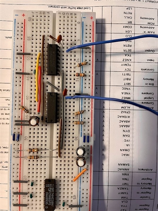
Schematic (my 2nd time using Kicad...I have no idea about layout of things so please forgive that). Obviously I am not showing the output connections from the CMP1312 that go to the on board LED's, LED matrix, speaker etc....
image
Eventually if it works, I would change the inputs from button switches to output from Arduino, turning the MUX pins on & off with delays in between to enter a program.

Well, the thing as shown in the schematic works: https://photos.app.goo.gl/8ZJtr1DJyEaJYaKHA

The thing is I don't understand why it works. I realized after setting it up and showing to someone else who mentioned that I didn't have the ground on the Trainer (9V battery power supply) connected to the ground for the MUXes (5V bench power supply). So the strange thing is that when I connect those 2 grounds together, I can no longer send signals to the Trainer from the MUX.  For the "onboard" keypad on the Trainer, I can only send input from keypad from any rows & column of keys except for the row & column MUX wires are attached to.

Can someone explain what is going on? Do I need a shared ground or is it not needed? Would it need to be shared if there was an Arduino connected instead of the buttons? I thought all I was needing to do was allow a single connection between one of the Rc-Rf input pins and one of the K1-K8 pins at a time that completes a circuit inside the CMP1312 which then registers it as a keypress.

In fact if I jumper across any pair of Rc-Rf input pins and K1-K8 pins (no MUX) with a single wire, a keypress is registered.  Should there be any signal sent from the MUX?  Help! Lost!!...

Thanks for any help!
Robert Opalko

  • Sign in to reply
  • Cancel

Top Replies

  • phoenixcomm
    phoenixcomm over 3 years ago in reply to opalko +2
    yes, that's correct 20 enable lines to the Arduino a Mega can handle that and more. As I do not know which lines are the output strobe find with the scope and no key press ( Data IN ) the other the Data…
  • phoenixcomm
    phoenixcomm over 3 years ago +1
    I think you have your grounds mixed up. it looks like there are 3 grounds Arduino TI CPU 9 VDC from the battery. So run the CPU ground and the Arduino ground LOGIC as one ground. i don't…
  • phoenixcomm
    0 phoenixcomm over 3 years ago

    I think you have your grounds mixed up. it looks like there are 3 grounds

    • Arduino
    • TI CPU
    • 9 VDC from the battery. 

    So run the CPU ground and the Arduino ground LOGIC as one ground. image

    i don't know why you picked that IC its an analog mux. what you need is something like a small relay on-off only two states or you can use these  CDx4HCT125 or 74LS125 are quadruple Buffers with 3-State Outputs. Im not sure which way the TI thing pulses the output lines [for giggles say its the column] (DATA IN, the DATA OUTPUT goes to the other row line this takes the place of the switch. ok  now for the Arduino goes to the enable 

    imagejust one more thing I think that you will be better off with the TTL74LS version as both CPUs use TTL levels and you will net 5 ICs to do the job. 

    Cris H

    • Cancel
    • Vote Up +1 Vote Down
    • Sign in to reply
    • Verify Answer
    • Cancel
  • opalko
    0 opalko over 3 years ago in reply to phoenixcomm

    Thank you. I think I picked the 4051 because I don't know what I am doing, HA!  So the CPU ground and the ground from the battery are not the same?! I didn't realize that and now not clear on the difference between the two.

     I will have to think through the 74LS125 connections. Am I not going to need 20 ENABLE output lines from the Arduino? I think I am missing how the connections go on both the Arduino and CPU....

    • Cancel
    • Vote Up 0 Vote Down
    • Sign in to reply
    • Verify Answer
    • Cancel
  • phoenixcomm
    0 phoenixcomm over 3 years ago in reply to opalko

    yes, that's correct 20 enable lines to the Arduino a Mega can handle that and more. As I do not know which lines are the output strobe find with the scope and no key press ( Data IN ) the other the Data Outputs. that is to the buffer. basically,T you are going to use the buffer as a switch.  Try this with on package first. 

    A much easier way would to find a serial port on the beast. the manual for the TMS 1000 is here

    . according to the link you provided it states there are only 128 nibbles or 64 bytes to play with and NO IO

    NICE TOY and start fresh and just use the Arduino. LOL Scream

    • Cancel
    • Vote Up +2 Vote Down
    • Sign in to reply
    • Verify Answer
    • Cancel
  • opalko
    0 opalko over 3 years ago in reply to phoenixcomm

    Ah - I think I get it. Could I not go from the Arduino (Uno) to a MUX (digital MUX??) for the enable lines ?

    • Cancel
    • Vote Up 0 Vote Down
    • Sign in to reply
    • Verify Answer
    • Cancel
  • phoenixcomm
    0 phoenixcomm over 3 years ago in reply to opalko

    no not a MUX. but an IO EXPANDER and BTW The last Row of Keys are control keys I don't think you will need to emulate them.  from your scope pick looks like the R lines are the outputs// the expander will use the Wire lib but I don't want to put water on this BUT  What are you going to do in 54 bytes??????? Put the silly thing on a shelf and forget it.  Sorry. 

    • Cancel
    • Vote Up 0 Vote Down
    • Sign in to reply
    • Verify Answer
    • Cancel
  • opalko
    0 opalko over 3 years ago in reply to phoenixcomm

    Yes I know it's primitive and I don't plan to use it as such; I just wanted to see if it was possible to send the input another way. Here is someone that has repurposed the trainer for some kind of test equipment but he is using relays, as I think you suggested originally.
    http://www.polylith.com/~brendan/ClassicComputers/Tandy/uCptrTrain.html

    • Cancel
    • Vote Up 0 Vote Down
    • Sign in to reply
    • Verify Answer
    • Cancel
  • opalko
    0 opalko over 3 years ago in reply to phoenixcomm

    The lines Rc-Rf are pulsed as well as the 07 line that the "control keys" are in which includes a program increment key, reset etc. -albeit for a shorter pulse.

    It is a silly thing and I am fiddling around with it for fun. I didn't know about IO expanders so I've learned about another component. Thanks!

    I am still not clear on the difference between CPU (CMP1312 microcontroller) GND and battery ground on the SFMT. There is a direct connection between the 2 so why would it make a difference what the Arduino or breadboarded MUX circuit ground is connected to?

    • Cancel
    • Vote Up 0 Vote Down
    • Sign in to reply
    • Verify Answer
    • Cancel
element14 Community

element14 is the first online community specifically for engineers. Connect with your peers and get expert answers to your questions.

  • Members
  • Learn
  • Technologies
  • Challenges & Projects
  • Products
  • Store
  • About Us
  • Feedback & Support
  • FAQs
  • Terms of Use
  • Privacy Policy
  • Legal and Copyright Notices
  • Sitemap
  • Cookies

An Avnet Company © 2025 Premier Farnell Limited. All Rights Reserved.

Premier Farnell Ltd, registered in England and Wales (no 00876412), registered office: Farnell House, Forge Lane, Leeds LS12 2NE.

ICP 备案号 10220084.

Follow element14

  • X
  • Facebook
  • linkedin
  • YouTube