element14 Community
element14 Community
    Register Log In
  • Site
  • Search
  • Log In Register
  • About Us
  • Community Hub
    Community Hub
    • What's New on element14
    • Feedback and Support
    • Benefits of Membership
    • Personal Blogs
    • Members Area
    • Achievement Levels
  • Learn
    Learn
    • Ask an Expert
    • eBooks
    • element14 presents
    • Learning Center
    • Tech Spotlight
    • STEM Academy
    • Webinars, Training and Events
    • Learning Groups
  • Technologies
    Technologies
    • 3D Printing
    • FPGA
    • Industrial Automation
    • Internet of Things
    • Power & Energy
    • Sensors
    • Technology Groups
  • Challenges & Projects
    Challenges & Projects
    • Design Challenges
    • element14 presents Projects
    • Project14
    • Arduino Projects
    • Raspberry Pi Projects
    • Project Groups
  • Products
    Products
    • Arduino
    • Avnet Boards Community
    • Dev Tools
    • Manufacturers
    • Multicomp Pro
    • Product Groups
    • Raspberry Pi
    • RoadTests & Reviews
  • Store
    Store
    • Visit Your Store
    • Choose another store...
      • Europe
      •  Austria (German)
      •  Belgium (Dutch, French)
      •  Bulgaria (Bulgarian)
      •  Czech Republic (Czech)
      •  Denmark (Danish)
      •  Estonia (Estonian)
      •  Finland (Finnish)
      •  France (French)
      •  Germany (German)
      •  Hungary (Hungarian)
      •  Ireland
      •  Israel
      •  Italy (Italian)
      •  Latvia (Latvian)
      •  
      •  Lithuania (Lithuanian)
      •  Netherlands (Dutch)
      •  Norway (Norwegian)
      •  Poland (Polish)
      •  Portugal (Portuguese)
      •  Romania (Romanian)
      •  Russia (Russian)
      •  Slovakia (Slovak)
      •  Slovenia (Slovenian)
      •  Spain (Spanish)
      •  Sweden (Swedish)
      •  Switzerland(German, French)
      •  Turkey (Turkish)
      •  United Kingdom
      • Asia Pacific
      •  Australia
      •  China
      •  Hong Kong
      •  India
      •  Korea (Korean)
      •  Malaysia
      •  New Zealand
      •  Philippines
      •  Singapore
      •  Taiwan
      •  Thailand (Thai)
      • Americas
      •  Brazil (Portuguese)
      •  Canada
      •  Mexico (Spanish)
      •  United States
      Can't find the country/region you're looking for? Visit our export site or find a local distributor.
  • Translate
  • Profile
  • Settings
Experts, Learning and Guidance
  • Technologies
  • More
Experts, Learning and Guidance
Ask an Expert Forum MOSFETs in linear operation
  • Blog
  • Forum
  • Documents
  • Leaderboard
  • Files
  • Members
  • Mentions
  • Sub-Groups
  • Tags
  • More
  • Cancel
  • New
Join Experts, Learning and Guidance to participate - click to join for free!
Actions
  • Share
  • More
  • Cancel
Forum Thread Details
  • State Suggested Answer
  • Replies 33 replies
  • Answers 1 answer
  • Subscribers 289 subscribers
  • Views 7033 views
  • Users 0 members are here
Related
See a helpful answer?

Be sure to click 'more' and select 'suggest as answer'!

If you're the thread creator, be sure to click 'more' then 'Verify as Answer'!

MOSFETs in linear operation

ben0127
ben0127 over 3 years ago

Hi,

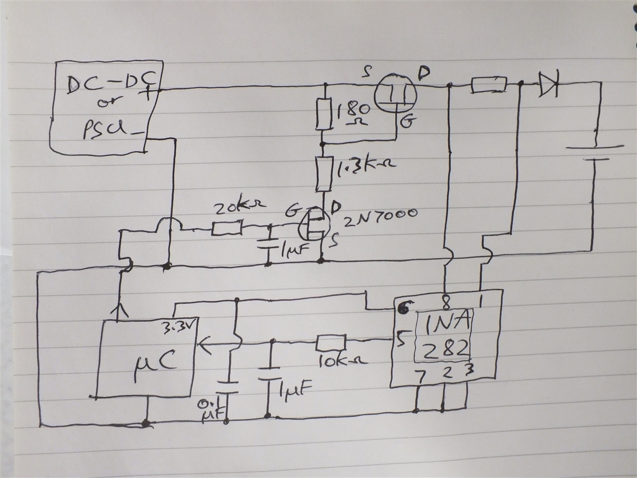
Im new here, first post, and am a fairly junior engineer so could do with some help regarding a charging circuit. I am designing a mosfet based current control circuit with a P-channel (needs to be high-side) and am having problems with the mosfet destroying itself. I have done some research into the use of mosfets in the linear region so I believe I am biasing it correctly and not putting much strain on it, keeping Vds low etc,  but when trying the circuit out it works for about 10 seconds before a wisp of smoke and charming aroma fills the lab. I have tried several different mosfets now and had the same problem with each of them, all setup to work comfortably within specs. 

After some more research I came across "Power Mosfets" which sounded like the answer to my problems, several articles I read talked about how standard mosfets cannot dissipate the heat being generated but power mosfets can. I started looking at the datasheets of some of these to select some samples but each one I looked at had the same issue which, with the knowledge I have so far, has ruled them out. The ZTC point on the transfer characteristics graph was very high.

My understanding of the operation of mosfets is that they need to be biased on (Vgs) above the ZTC point so that they are thermally stable. This is one of the key properties I have looked for in datasheets, along with the SOA, but what Im seeing with power mosfets is, for example, a ZTC point at 20A with a realistically useful maximum current of around 20A. This is of no use to me as there is no range. The standard mosfets have a much lower ZTC point so can be used to regulate current over a significant range which is what Im looking for. 

Im starting to doubt some of the things Ive learned about these devices and so definitely need some help with some questions:

Ive got used to thinking that I can only use mosfets above the ZTC point but these power mosfets look like using them below it would be necessary. Im wondering if it is safe to do so, as long as you have a feedback system to back off the current as it warms up?? If this is the case, is it safe to use at Vgs extending all the way down to the Vgs threshold? 

During research another confusing piece of info I came across, which completely contradicts what I had come to understand about power mosfets, was that they can fail in operation above the ZTC point even when within the SOA. I thought the whole point of a "power mosfet" was that it could handle operating in linear mode? Isnt this what differentiates it from a standard mosfet?

Im starting to wonder what it is Im missing with this as it seemed relatively simple to begin with so any help or advise on any of these points would be greatly appreciated.

  • Sign in to reply
  • Cancel

Top Replies

  • Andrew J
    Andrew J over 3 years ago in reply to michaelkellett +5
    I had to look up ZTC as well. Michael is making some useful points here: before blowing any more MOSFETs or spending money on buying more to blow in a similar manner, you should do a bit of research on…
  • dougw
    dougw over 3 years ago +3
    Have you calculated the maximum power that needs to be dissipated in your transistor? Are you familiar with how to calculate the amount of heat sinking you need based on the power levels? If you have amps…
  • michaelkellett
    michaelkellett over 3 years ago +3
    To make helpful comments we need more information. A schematic (with component types and values) and some pictures would be a good start. A specification always helps. Mostly power MOSFETs are not…
Parents
  • michaelkellett
    0 michaelkellett over 3 years ago

    To make helpful comments we need more information.

    A schematic (with component types and values) and some pictures would be a good start. A specification always helps.

    Mostly power MOSFETs are not operated with any regard at all to ZTC (and I even had to look it up).

    You would normally have some kind of feedback arrangment to control the gate voltage.

    BTW, you don't need P channel parts to make high side controllers.

    MK

    • Cancel
    • Vote Up +3 Vote Down
    • Sign in to reply
    • Verify Answer
    • Cancel
  • ben0127
    0 ben0127 over 3 years ago in reply to michaelkellett

    Thankyou, its interesting to hear that ZTC is largely ignored. That answers my question about the useful range I was looking for in the datasheets.

    Is there a disadvantage in using P-channel as opposed to N-channel?

    Apologies for the lack of specifics regarding circuitry and component values etc but Im just at the beginning stage of this and want to get a feel for how these operate. I dont have a complete finalised circuit or anything, just supporting components to operate the mosfet.

    Basically Im using a small mosfet to drop voltage across a resistor which is between gate and source of the main mosfet, producing the Vgs. This voltage is set (depending on the device used) at around 5.5V to produce 4 - 5A drain current and there is feedback to maintain the current - which I monitored. The devices I have tried are rated well beyond this and have power ratings of well over 100W. The IRF6218 for example has 250W max power rating and with Vds of 4V I am dissipating around 20W. 

    This is why I feel that there must be something fundamental I am missing because 20W in a 250W device surely shouldnt cause thermal failure in 10 seconds.

    • Cancel
    • Vote Up +1 Vote Down
    • Sign in to reply
    • Verify Answer
    • Cancel
  • javagoza
    0 javagoza over 3 years ago in reply to ben0127

    You're welcome. I have learned a lot with your question, the element14 community is great, always willing to help those of us who are just starting out.

    From the element14 Participation Guidelines and Code of Conduct

    "The element14 Community is intended to be a safe and inclusive space, free from violence, harassment, hate speech or exclusionary behaviour."

    "

    • Don’t judge – instead share your knowledge! Knowledge is not a competition – instead of judging people for what they don’t know (or seemingly haven't google searched for), help them. Elitism is not welcome, even unintended. Remember that different people have different approaches and may have valid reasons for why they're asking.
      • Similarly 'back handed' assistance which criticizes the person asking and then provides the answer requested is also not tolerated and can be seen as a form of emotional abuse.

    "

    • Cancel
    • Vote Up +2 Vote Down
    • Sign in to reply
    • Verify Answer
    • Cancel
  • Andrew J
    0 Andrew J over 3 years ago in reply to ben0127

    What Javagoza says: you'll find that Element14 isn't like other sites and you won't get any grief at all for asking questions or posting things up.  You'll get as much help as you ask for, given politely and with encouragement.

    • Cancel
    • Vote Up +1 Vote Down
    • Sign in to reply
    • Verify Answer
    • Cancel
  • dougw
    0 dougw over 3 years ago in reply to ben0127

    Hopefully the comments here don't sound like flames - that is not a motive on this site. Many of us have similar stories to yours. Shy about publishing ideas and not into social media. I also burned my finger on my first linear power supply design. What we learn from these experiences is more valuable than the components we smoke.

    • Cancel
    • Vote Up +1 Vote Down
    • Sign in to reply
    • Verify Answer
    • Cancel
  • ben0127
    0 ben0127 over 3 years ago in reply to ben0127

    Morning folks,

    This is my circuit, essentially a battery charger but the point is that the charge rate is fully controlled. The supply will be a DC-DC with some level of output control for the purpose of reducing voltage across the mosfet. There will be other circuitry in there as well for detection of faults etc but the main design is shown. The 1.3k resistor is several in series to handle the power, this is to drop most of the remaining voltage (protecting the 2N7000) as the supply is around 50V (for 48V battery). This drive circuit still needs work but the focus for now is on the main mosfet.

    Im thinking about maybe using this as a module which can be paralleled to get more current, the mosfets could be individually monitored that way rather than just assuming that each mosfet is taking the same current as the others.

    image

    • Cancel
    • Vote Up 0 Vote Down
    • Sign in to reply
    • Verify Answer
    • Cancel
  • michaelkellett
    0 michaelkellett over 3 years ago in reply to ben0127

    First thought, you have a feedback loop where you are sensing the current with theresistor and  INA282, measuring the signal with the processsor ADC, working out the feedback required, driving the processor DAC and then controlling the 2N7000 via a filter with a 20ms time constant.

    I was going to say that this is a very bad way to do it, but I'll settle for observing that it is a very unusual way.

    The feedback loop will alwas be very slow because the micro's ADC and DAC conversion are inside it. This means that if you short the output the MOSFET will alwas blow !

    A much neater way to do it is use an anlogue voltage feedback loop and control the reference voltage with the processor.

    I'm suspicious of the 48V charge voltage - real '48V'  batteries charge between roughly 40 and 52V (lead acid) and maybe 35 - 54V (lithium ion). The range can be bigger than this.

    So I think your PSU will need to provide maybe 56V and deliver full charge current with the load at 40V.

    There a a million and one different ways of doing this.

    You can buy controller chips that manage a switching power supply (eg LTC 4000) but I think you might find this very hard to work with.

    It's much easier to use low side current sensing, but there is a disadvanatage that your controller 0V and the batteries load 0V are not the same.

    You don't need such a low gate source resistor on the MOSFET so you can reduce the power in the level shifter.

    This type of design work is vastly facilitated by using a ciruit simulator.

    I suggest that you donwload LTSPice from www.analog.com. It's free and very widely used.

    I've thrown together (very quickly) a simple all discrete part, linbear regulator. This is nowhere near a final circuit but it might help you get started.

    V2 and V4 between them are the control input or reference.

    Q1 and Q2 make a diff amp which compares a proportion of the output with the reference and adjustes the drive to M1 via the emitter follower Q3.

    V3 and R1  represent the battery.

    R3 senses the battery current (not used at the moment, this is waht your micr can measure and decide how to tweak the drive voltage to adjust the charge current.

    It's easy to add hardware current limit with an NPN transistor driven by the voltage drop on R3, but there are other better ways.

    If you get this design into LTSpice and spend soem time playing both with the tool and the circuit you'll get a much better idea of where you are going.

    But you really need to pin down the spec:

    range of input volts, range of output volts, max current, max voltage before battery explosion, must it stand shorts to ground as well as across the battery, operating temperature range, accuracy of current and voltage measurement and must the battery 0V be a system common rail , to name just a few things you need to know.

    image

    MK

    .

    • Cancel
    • Vote Up +2 Vote Down
    • Sign in to reply
    • Verify Answer
    • Cancel
  • scottiebabe
    0 scottiebabe over 3 years ago in reply to ben0127

    For a one off prototype, I would just use the classic op-amp servo'd current source only in a high-side topology such as:

    image

    Source: https://www.ti.com/lit/an/slaa867/slaa867.pdf

    OP-amp A1 can be powered off 5 V (or similar).

    OP-Amp A2 would need a supply referenced to the Vin. The can be done with a simple shunt regulator, such as a zener diode or a TL431. 

    • Cancel
    • Vote Up +1 Vote Down
    • Sign in to reply
    • Verify Answer
    • Cancel
  • ben0127
    0 ben0127 over 3 years ago in reply to michaelkellett

    First of all I would like to say thankyou for putting what must have been a very significant amount of time into your reply, with constructive criticism, alternate ideas and an entire circuit design. Unfortunately, reading through the points made there seems to be quite a lot of misunderstanding of the circuit. This may well be my fault for not explaining everything but I was attempting to not draw attention to things that at the moment are not the focus.

    The thread was really about making sure I was not misusing or abusing the main mosfet with my circuitry, although I dont want to sound ungrateful for the opinions and advice on the whole circuit. 

    I would like to go through some of the points just to clear things up:

    The feedback - this was never meant to replicate a classic closed loop control system, it would be useless in that respect, it was just basic feedback to nudge the gate drive if and when it needs it. That probably sounds ridiculous but its not so much that I think its a good way of doing feedback in the conventional sense, although its perfectly adequate for this purpose, but more that I like the idea of the micro being involved, it knows how hard its driving the gate etc.  The 20ms filter you mentioned is there to remove the switching of the 2N7000 drive signal. I use PWM from the micro as I get a much better resolution than that offered by the DAC. As mentioned in the post I am still working on the drive circuitry as it has other issues. 

    If the output goes short the system will not rely on the feedback system, the battery voltage will be seen as 0V (or extremely low) and the mosfet will be switched off, assuming that the battery PCM doesnt get there first and disconnect the battery. 

    Regarding the battery voltage I mentioned (48V) I can see where this caused confusion and slightly regret mentioning it, but it wasnt meant to draw attention to itself. Just for clarity the battery is Lithium with a range of 33.6V to 50.4V. 

    Low side current sensing, indeed low side anything, causes problems which are unacceptable in this system. Ground must be ground.

    The gate-source resistor on the main mosfet is as low as it is for improved resolution. Controlling the main mosfet over a wide range of charge current and with accuracy isnt easy and as I mentioned earlier its still being improved.

    LTspice is great and Ive used it quite a bit but it doesnt tell you that your mosfets going to blow up :)

    Youve gone to a lot of trouble designing a circuit which is above and beyond, thankyou. Even if I dont change my approach it shows me more established methods which are good tools to keep in the box. My circuit was not intended to be a reinvention of the wheel, Im part of an innovation centre which is investigating new smarter charging methods.

    My initial reason for reaching out with this thread was that the mosfets kept blowing but the thermal issues causing the problem are understood now so thats sorted out.  Thanks to you and all others that have replied for your help.

    • Cancel
    • Vote Up +1 Vote Down
    • Sign in to reply
    • Verify Answer
    • Cancel
  • michaelkellett
    0 michaelkellett over 3 years ago in reply to ben0127

    Thanks for explaining where you are with this.

    I think you will always have trouble using power MOSFETs in linear mode without an analogue feedback loop to control them, the problem with controlling the gate precisely is that the relationship between gate source voltage and drain source current is not well defined.

    Most of the modern power MOSFET specs seem to be concerned with switching them hard on or off.

    Good luck with your project, perhaps you can post some more about it as it progresses.

    MK

    • Cancel
    • Vote Up +3 Vote Down
    • Sign in to reply
    • Verify Answer
    • Cancel
  • ben0127
    0 ben0127 over 3 years ago in reply to michaelkellett

    Ive been thinking about what you said regarding linear mode without analogue feedback as Ive been able to do some testing with mosfets over the last day or two. All is running smoothly now with good heatsinking so Ive been able to see my feedback solution in operation and it seems to be working very nicely but I cant help being slightly nervous, considering your comment.

    Its really crude but seemed like it might be good enough considering that the mosfet doesnt need a closed loop control system to operate (as opposed to an SMPS chip for example). Essentially the current value is read by the ADC and a simple algorithm adjusts the duty cycle to maintain the desired current. 

    It seems to work exactly as expected with a significant reduction in duty cycle initially as the mosfet warms up, then it settles and stays put. My tests include mosfet temperature so I can see the heating tracking with the algorithm adjustments, which presumably is down to the gate threshold reducing with heat as its operation is below the ZTC point. 

    Once everything settled down (within about 5 minutes) and was left for another 10 minutes or so I tested the feedback by putting my fingers over the drive mosfet (cooling it). The result was as expected, the duty cycle started increasing quickly to compensate but the current held nicely. When I let go the opposite happened and it returned. 

    Im really interested to know what you think, it seems to work great but am I fooling myself? 

    • Cancel
    • Vote Up 0 Vote Down
    • Sign in to reply
    • Verify Answer
    • Cancel
  • michaelkellett
    0 michaelkellett over 3 years ago in reply to ben0127

    When everything is about right I would expect it to work OK as you describe. Might be worth checking that the currrent isn't fluctuating which might be an indication of instability. If you wind up the gain enough in your control loop you will be able to make it unstable.

    My main worries would be the slow response to serious fault conditions.

    (It is possible that this doesn't matter in your application.)

    I would normally include a software bug as a fault condition to be protected against.

    Since failures in chargers for big Lion batteries have such serious consequences (don't trust the internal protection - that's just insurance) I would like to see processor independent over voltage and over current protection.

    Overcurrents will happen when some fault shorts the output to ground, on a good day this blow the MOSFET open circuit, on a bad day it will blow it short circuit and the large current into the battery may pull the supply down a bit leaving you in a very bad position.

    The other overcurrent that can happen is when the processor (during development) decides to set maximum possible current (PWM output sticks high).

    I'm a bit busy right now but I may be able to get back to this tomorrow morning. Let me know if you need some tips re. how to limit the MOSFET current.

    For thermal protection I would glue some electro-mechnical thermal switches to the battery.

    MK

    • Cancel
    • Vote Up +2 Vote Down
    • Sign in to reply
    • Verify Answer
    • Reject Answer
    • Cancel
Reply
  • michaelkellett
    0 michaelkellett over 3 years ago in reply to ben0127

    When everything is about right I would expect it to work OK as you describe. Might be worth checking that the currrent isn't fluctuating which might be an indication of instability. If you wind up the gain enough in your control loop you will be able to make it unstable.

    My main worries would be the slow response to serious fault conditions.

    (It is possible that this doesn't matter in your application.)

    I would normally include a software bug as a fault condition to be protected against.

    Since failures in chargers for big Lion batteries have such serious consequences (don't trust the internal protection - that's just insurance) I would like to see processor independent over voltage and over current protection.

    Overcurrents will happen when some fault shorts the output to ground, on a good day this blow the MOSFET open circuit, on a bad day it will blow it short circuit and the large current into the battery may pull the supply down a bit leaving you in a very bad position.

    The other overcurrent that can happen is when the processor (during development) decides to set maximum possible current (PWM output sticks high).

    I'm a bit busy right now but I may be able to get back to this tomorrow morning. Let me know if you need some tips re. how to limit the MOSFET current.

    For thermal protection I would glue some electro-mechnical thermal switches to the battery.

    MK

    • Cancel
    • Vote Up +2 Vote Down
    • Sign in to reply
    • Verify Answer
    • Reject Answer
    • Cancel
Children
  • ben0127
    0 ben0127 over 3 years ago in reply to michaelkellett

    Thanks for that, no rush to come back if you think of anything else, whenever you have time. 

    Fault conditions will be dealt with later on, the feedback is only to hold the current stable. Good points made though.

    • Cancel
    • Vote Up 0 Vote Down
    • Sign in to reply
    • Verify Answer
    • Cancel
element14 Community

element14 is the first online community specifically for engineers. Connect with your peers and get expert answers to your questions.

  • Members
  • Learn
  • Technologies
  • Challenges & Projects
  • Products
  • Store
  • About Us
  • Feedback & Support
  • FAQs
  • Terms of Use
  • Privacy Policy
  • Legal and Copyright Notices
  • Sitemap
  • Cookies

An Avnet Company © 2025 Premier Farnell Limited. All Rights Reserved.

Premier Farnell Ltd, registered in England and Wales (no 00876412), registered office: Farnell House, Forge Lane, Leeds LS12 2NE.

ICP 备案号 10220084.

Follow element14

  • X
  • Facebook
  • linkedin
  • YouTube