Hello,
I am quite new to C programming and Microchip programming in general but I did something for a personal project however I am not sure what and if I am doing something wrong.
I am trying to read the voltage from 6 thermocouples and eventually convert it into actual temperature units in order to control a relay. Now I want to mention that I want to achieve a good precision, perhaps 0.1 degreess or better if possible.
For that, I am using really precise J type thermocouples. The thermoelectric voltage in milivolts for these thermocouples is for example, 27.5mV at 500C. At 20C, it is just 1.2mV.
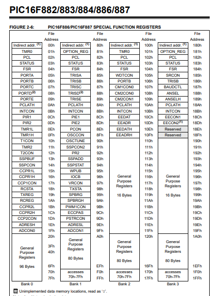
I worked on this project for a bit, in order to get these voltages but I am not sure what I am doing wrong. I am using the PIC16F887 because I feel like this can be done on this MCU and because it is widely available.
Project is in MPLAB and XC8 compiler.
/**************************************************************************************

  Thermocouple reading.

***************************************************************************************/


#define _XTAL_FREQ  16000000

#include <stdint.h>
#include "CONFIG.h"


void Initialise_Analogue_Pins(){
    ANSELbits.ANS1 = 1;
    ANSELbits.ANS2 = 1;
    ANSELbits.ANS3 = 1;
    ANSELbits.ANS4 = 1;
    ANSELbits.ANS5 = 1;
    ANSELbits.ANS6 = 1;
}

int Upper_Zone_1(){
    ADCON0bits.CHS = 0b0001;        // Select AN1.
    ADCON1bits.ADFM = 1;
    ADCON0bits.ADON = 1;
    PIE2bits.C1IE = 0;
    PIR2bits.C1IF = 0;
    __delay_ms(50);
    while(ADCON0bits.GO_DONE);
    return((ADRESH<<8) + ADRESL);
}

int Upper_Zone_2(){
    ADCON0bits.CHS = 0b0010;        // Select AN2.
    ADCON1bits.ADFM = 1;
    ADCON0bits.ADON = 1;
    PIE2bits.C1IE = 0;
    PIR2bits.C1IF = 0;
    __delay_ms(50);
    while(ADCON0bits.GO_DONE == 1);
    return((ADRESH<<8) + ADRESL);
}

int Upper_Zone_3(){
    ADCON0bits.CHS = 0b0011;        // Select AN3.
    ADCON1bits.ADFM = 1;
    ADCON0bits.ADON = 1;
    PIE2bits.C1IE = 0;
    PIR2bits.C1IF = 0;
    __delay_ms(50);
    while(ADCON0bits.GO_DONE == 1);
    return((ADRESH<<8) + ADRESL);
}

int Upper_Zone_4(){
    ADCON0bits.CHS = 0b0100;        // Select AN4.
    ADCON1bits.ADFM = 1;
    ADCON0bits.ADON = 1;
    PIE2bits.C1IE = 0;
    PIR2bits.C1IF = 0;
    __delay_ms(50);
    while(ADCON0bits.GO_DONE == 1);
    return((ADRESH<<8) + ADRESL);
}

int Upper_Zone_5(){
    ADCON0bits.CHS = 0b0101;        // Select AN5.
    ADCON1bits.ADFM = 1;
    ADCON0bits.ADON = 1;
    PIE2bits.C1IE = 0;
    PIR2bits.C1IF = 0;
    __delay_ms(50);
    while(ADCON0bits.GO_DONE == 1);
    return((ADRESH<<8) + ADRESL);
}

int Upper_Zone_6(){
    ADCON0bits.CHS = 0b0110;        // Select AN6.
    ADCON1bits.ADFM = 1;
    ADCON0bits.ADON = 1;
    PIE2bits.C1IE = 0;
    PIR2bits.C1IF = 0;
    __delay_ms(50);
    while(ADCON0bits.GO_DONE == 1);
    return((ADRESH<<8) + ADRESL);
}

// Main function
void main() {
    int Upper_Zone_1_Temp, Upper_Zone_2_Temp, Upper_Zone_3_Temp, Upper_Zone_4_Temp, Upper_Zone_5_Temp, Upper_Zone_6_Temp;

    Initialise_Analogue_Pins();     // Initialise analogue pins.
    //INTCON = 0xC0;                  // Enable global and peripheral interrupts

    while(1) {
        Upper_Zone_1_Temp = Upper_Zone_1();
        //Upper_Zone_2_Temp = Upper_Zone_2();
        //Upper_Zone_3_Temp = Upper_Zone_3();
        //Upper_Zone_4_Temp = Upper_Zone_4();
        //Upper_Zone_5_Temp = Upper_Zone_5();
        //Upper_Zone_6_Temp = Upper_Zone_6();
    }
}
Here is the header file:
#ifndef XC_HEADER_TEMPLATE_H
#define	XC_HEADER_TEMPLATE_H


// PIC16F887 Configuration Bit Settings

// 'C' source line config statements

// CONFIG1
#pragma config FOSC = HS        // Oscillator Selection bits (HS oscillator: High-speed crystal/resonator on RA6/OSC2/CLKOUT and RA7/OSC1/CLKIN)
#pragma config WDTE = OFF       // Watchdog Timer Enable bit (WDT disabled and can be enabled by SWDTEN bit of the WDTCON register)
#pragma config PWRTE = ON      // Power-up Timer Enable bit (PWRT disabled)
#pragma config MCLRE = ON       // RE3/MCLR pin function select bit (RE3/MCLR pin function is MCLR)
#pragma config CP = OFF          // Code Protection bit (Program memory code protection is enabled)
#pragma config CPD = OFF         // Data Code Protection bit (Data memory code protection is enabled)
#pragma config BOREN = ON       // Brown Out Reset Selection bits (BOR enabled)
#pragma config IESO = OFF        // Internal External Switchover bit (Internal/External Switchover mode is enabled)
#pragma config FCMEN = OFF       // Fail-Safe Clock Monitor Enabled bit (Fail-Safe Clock Monitor is enabled)
#pragma config LVP = OFF         // Low Voltage Programming Enable bit (RB3/PGM pin has PGM function, low voltage programming enabled)

// CONFIG2
#pragma config BOR4V = BOR40V   // Brown-out Reset Selection bit (Brown-out Reset set to 4.0V)
#pragma config WRT = OFF        // Flash Program Memory Self Write Enable bits (Write protection off)

// #pragma config statements should precede project file includes.
// Use project enums instead of #define for ON and OFF.

#include <xc.h>


#endif	/* XC_HEADER_TEMPLATE_H */