element14 Community
element14 Community
    Register Log In
  • Site
  • Search
  • Log In Register
  • Community Hub
    Community Hub
    • What's New on element14
    • Feedback and Support
    • Benefits of Membership
    • Personal Blogs
    • Members Area
    • Achievement Levels
  • Learn
    Learn
    • Ask an Expert
    • eBooks
    • element14 presents
    • Learning Center
    • Tech Spotlight
    • STEM Academy
    • Webinars, Training and Events
    • Learning Groups
  • Technologies
    Technologies
    • 3D Printing
    • FPGA
    • Industrial Automation
    • Internet of Things
    • Power & Energy
    • Sensors
    • Technology Groups
  • Challenges & Projects
    Challenges & Projects
    • Design Challenges
    • element14 presents Projects
    • Project14
    • Arduino Projects
    • Raspberry Pi Projects
    • Project Groups
  • Products
    Products
    • Arduino
    • Avnet & Tria Boards Community
    • Dev Tools
    • Manufacturers
    • Multicomp Pro
    • Product Groups
    • Raspberry Pi
    • RoadTests & Reviews
  • About Us
  • Store
    Store
    • Visit Your Store
    • Choose another store...
      • Europe
      •  Austria (German)
      •  Belgium (Dutch, French)
      •  Bulgaria (Bulgarian)
      •  Czech Republic (Czech)
      •  Denmark (Danish)
      •  Estonia (Estonian)
      •  Finland (Finnish)
      •  France (French)
      •  Germany (German)
      •  Hungary (Hungarian)
      •  Ireland
      •  Israel
      •  Italy (Italian)
      •  Latvia (Latvian)
      •  
      •  Lithuania (Lithuanian)
      •  Netherlands (Dutch)
      •  Norway (Norwegian)
      •  Poland (Polish)
      •  Portugal (Portuguese)
      •  Romania (Romanian)
      •  Russia (Russian)
      •  Slovakia (Slovak)
      •  Slovenia (Slovenian)
      •  Spain (Spanish)
      •  Sweden (Swedish)
      •  Switzerland(German, French)
      •  Turkey (Turkish)
      •  United Kingdom
      • Asia Pacific
      •  Australia
      •  China
      •  Hong Kong
      •  India
      • Japan
      •  Korea (Korean)
      •  Malaysia
      •  New Zealand
      •  Philippines
      •  Singapore
      •  Taiwan
      •  Thailand (Thai)
      • Vietnam
      • Americas
      •  Brazil (Portuguese)
      •  Canada
      •  Mexico (Spanish)
      •  United States
      Can't find the country/region you're looking for? Visit our export site or find a local distributor.
  • Translate
  • Profile
  • Settings
Experts, Learning and Guidance
  • Technologies
  • More
Experts, Learning and Guidance
Ask an Expert Forum Upcycling a broken weather station: how to drive LCD segments from 3v3 logic?
  • Blog
  • Forum
  • Documents
  • Leaderboard
  • Files
  • Members
  • Mentions
  • Sub-Groups
  • Tags
  • More
  • Cancel
  • New
Join Experts, Learning and Guidance to participate - click to join for free!
Actions
  • Share
  • More
  • Cancel
Forum Thread Details
  • State Not Answered
  • Replies 12 replies
  • Subscribers 308 subscribers
  • Views 2281 views
  • Users 0 members are here
  • lcd
  • i2c
  • lowpower
  • spi
Related
See a helpful answer?

Be sure to click 'more' and select 'suggest as answer'!

If you're the thread creator, be sure to click 'more' then 'Verify as Answer'!

Upcycling a broken weather station: how to drive LCD segments from 3v3 logic?

obones
obones over 2 years ago

I have here a Lacrosse Techonlogy / StarMeteo WD-4103F weather station that had misbehaving user buttons.
I thus opened it in order to fix them which I believe I did well. Before putting it back together, I wanted to test it and because the battery older is not on the PCB, I decided to power it from my benchtop power supply. And that's when a bug occurred in my mind which somehow thought that two C batteries would be 6V.

The LCD was a lot darker that usual, but it seemed to work for a bit. Nothing smoked but by the time I figured my error, I believe damage was done to the "brains" of that board.
Now, when I power it with regular batteries (or 3V) it starts up, but seems to deadlock after a while as can be seen on that video:

You don't have permission to edit metadata of this video.
Edit media
x
image
Upload Preview
image

I contacted the manufacturer support center but, unsurprisingly, they did not even reply to me.

Considering that the outside sensor can be read just well with an RTL-SDR and rtl_433, I have the project of changing the brains of the device, using the MAX32666FTHR board that I have sitting on my desk. It's a very low power device which is really appropriate in such a battery powered project, and because it supports BLE, I figured it could talk to one of the ESP32s that I already have around the house. This would make for this:

ESP32 gathers weather forecast from Internet and stores it, MAX32666 connects whenever it sees fit and displays it on the WD-4103F LCD.

I started my thought process by studying the main PCB which looks like this:

image

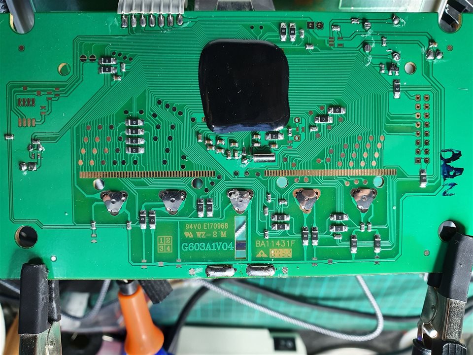
The row of pads at the center is what "touches" the LCD interface and so I would have to control it this way.

Having been allowed to use an X-Ray imager as an exceptional favor, I was able to see through the resin patch and this leads to this photo montage where I colored each track:

image

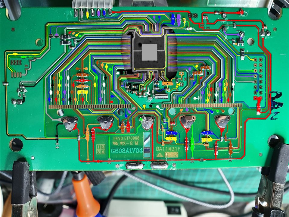
What's very interesting is that some LCD pads are connected together, and each have a test pad exposed onto which I could solder a connection wire.

My issue, and the object of my question, is how can I connect the LCD segments to the MAX32666?
I understand that LCDs require specific high voltage to operate but are there specialized low power chips that do this? And ideally a SPI or I2C solution because the dev board definitely does not have enough IO pins available for all LCD segments that need to be driven.

Many thanks in advance for any suggestion here.

  • Sign in to reply
  • Cancel

Top Replies

  • michaelkellett
    michaelkellett over 2 years ago +2
    I think you are unlikely to succeed here. The LCD display has at least 190 segments so you would need a driver chip with at least 28 pins (14 * 14 = 196). The MAX won't ever do this directly. It will…
  • dougw
    dougw over 2 years ago +1
    Have you checked the voltages on the card? Maybe some power supply component has sacrificed itself and replacing it will bring everything back to life.
  • shabaz
    shabaz over 2 years ago +1
    Hi, This is going to be very difficult. There are enough LCD segments on the display, that it won't be 'statically-driven' and will instead have multiplexed signals, using non-binary voltages, i.e. there…
  • dougw
    0 dougw over 2 years ago

    Have you checked the voltages on the card? Maybe some power supply component has sacrificed itself and replacing it will bring everything back to life.

    • Cancel
    • Vote Up +1 Vote Down
    • Sign in to reply
    • Verify Answer
    • Cancel
  • shabaz
    0 shabaz over 2 years ago

    Hi,

    This is going to be very difficult. There are enough LCD segments on the display, that it won't be 'statically-driven' and will instead have multiplexed signals, using non-binary voltages, i.e. there are voltages in-between high and low. NXP has chips that can perform this exercise, so you'd need to use that, because the MAX3.. chip won't have that capability as far as I can tell. Occasionally some microcontrollers have built-in LCD driver capability, but it's rare, and it would be unlikely to support so many LCD segments. Even with the correct NXP chip, you'd need to experiment (it can be done with a battery, resistor and a couple of wires) to see which segment goes to which connection. This is a lot easier with a statically-driven display (but even then, you'd preferably need to use a LCD driver chip, since the waveform is AC, even though it is using just two voltage levels, but it's OK to briefly apply a low DC voltage, ballpark 3-5V, to see which segment gets activated). 

    In summary, it will be extremely difficult to successfully interface directly to the LCD screen with a different microcontroller.

    • Cancel
    • Vote Up +1 Vote Down
    • Sign in to reply
    • Verify Answer
    • Cancel
  • michaelkellett
    0 michaelkellett over 2 years ago

    I think you are unlikely to succeed here. The LCD display has at least 190 segments so you would need a driver chip with at least 28 pins (14 * 14 = 196). The MAX won't ever do this directly.

    It will almost certainly be much cheaper to buy a little graphics display with a serial interface. It will also save you a huge amount of effort in trying to work out how the existing LCD is connected.

    MK

    • Cancel
    • Vote Up +2 Vote Down
    • Sign in to reply
    • Verify Answer
    • Cancel
  • michaelkellett
    0 michaelkellett over 2 years ago in reply to shabaz

    Our messages crossed in the ether !

    MK

    • Cancel
    • Vote Up +1 Vote Down
    • Sign in to reply
    • Verify Answer
    • Cancel
  • colporteur
    0 colporteur over 2 years ago

    I count myself in the group of fixers that have inadvertently applied the wrong voltage. Reasons regardless shite doesn't work after.

    Not to condone this solution, I have purchased new units to replace what I have smoked. I hope you are not in that situation.

    • Cancel
    • Vote Up 0 Vote Down
    • Sign in to reply
    • Verify Answer
    • Cancel
  • obones
    0 obones over 2 years ago in reply to dougw

    Well, nothing came up as obvious on the main board as depicted above.
    But there is a secondary board that is quite certain to be the RF receiver and it might that this is the one that is somewhat fried, leading to a deadlock on the main one that waits on a chip that may never reply.

    • Cancel
    • Vote Up 0 Vote Down
    • Sign in to reply
    • Verify Answer
    • Cancel
  • obones
    0 obones over 2 years ago in reply to shabaz

    Thanks, that's unfortunately close to my own conclusion.
    Well, at least I learnt something new out of this, I did not know there was LCDs with various "levels" to drive different segments.
    I sure miss 25 years ago when I discovered electronics and things were much simpler and accessible to the hobbyist...

    • Cancel
    • Vote Up 0 Vote Down
    • Sign in to reply
    • Verify Answer
    • Cancel
  • obones
    0 obones over 2 years ago in reply to michaelkellett

    Finding a new display that fits in that enclosure and is easily addressable while being cheap is something that I'm having a hard time doing.
    I mean, it's a 9cm x 9cm square area when most displays are 16:9 / 16:10 aspect ratio.
    The ED050SC epaper display seems to be roughly the correct size with a somewhat acceptable price (~20€) but a quick search could not lead to any documentation on how to drive it easily.
    Would you, by chance, have any suggestions in that matter?

    • Cancel
    • Vote Up 0 Vote Down
    • Sign in to reply
    • Verify Answer
    • Cancel
  • obones
    0 obones over 2 years ago in reply to colporteur

    To be honest, the replacement is already there and working in its place because other members of the family relied on it working.
    But I don't like throwing away things that can still be of use, not at least until I have exhausted all reuse possibilities.

    Sadly, I think this one will join quite a few other things to the recycling bin...

    • Cancel
    • Vote Up 0 Vote Down
    • Sign in to reply
    • Verify Answer
    • Cancel
  • michaelkellett
    0 michaelkellett over 2 years ago in reply to obones

    From a quick look at internet it's obsolete and unobtainable. I couldn't find a datasheet. If you have the datasheet and can get the display then post the datsheet here (or a link to it) and I'll take a look. I wouldn't expect too much joy here because the description I found said it had a parallel interface.

    MK

    • Cancel
    • Vote Up 0 Vote Down
    • Sign in to reply
    • Verify Answer
    • Cancel
>
element14 Community

element14 is the first online community specifically for engineers. Connect with your peers and get expert answers to your questions.

  • Members
  • Learn
  • Technologies
  • Challenges & Projects
  • Products
  • Store
  • About Us
  • Feedback & Support
  • FAQs
  • Terms of Use
  • Privacy Policy
  • Legal and Copyright Notices
  • Sitemap
  • Cookies

An Avnet Company © 2026 Premier Farnell Limited. All Rights Reserved.

Premier Farnell Ltd, registered in England and Wales (no 00876412), registered office: Farnell House, Forge Lane, Leeds LS12 2NE.

ICP 备案号 10220084.

Follow element14

  • X
  • Facebook
  • linkedin
  • YouTube