


I am planning to make an DIY oscilloscope. I was looking at other projects and found this circuit which is being used at the Analog front end of the scope. The basic functionality is protection and voltage swing shifting to match the voltage range of the GPIO pin(RPi Pico is being used here)
Project link: https://www.hackster.io/sandy-roberts2/stripboard-oscilloscope-4229ee
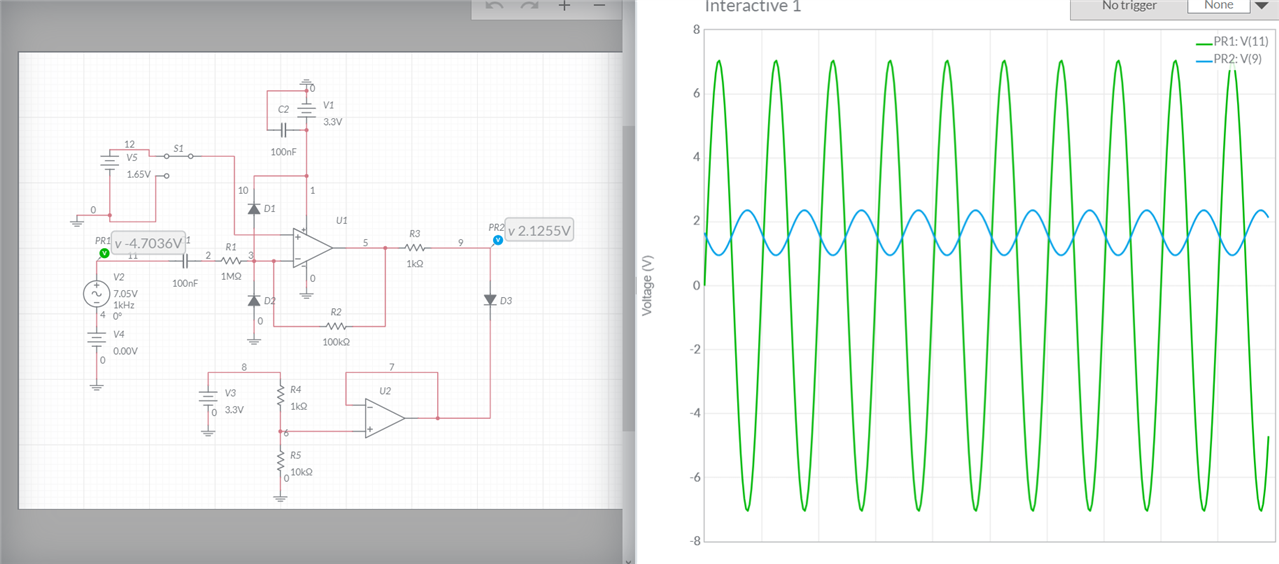
I have simulated this circuit in the Multisim Live: https://www.multisim.com/content/UKVp8oVDBb4qX6idoeaCSi/oscilloscope-analog-front-end/open/
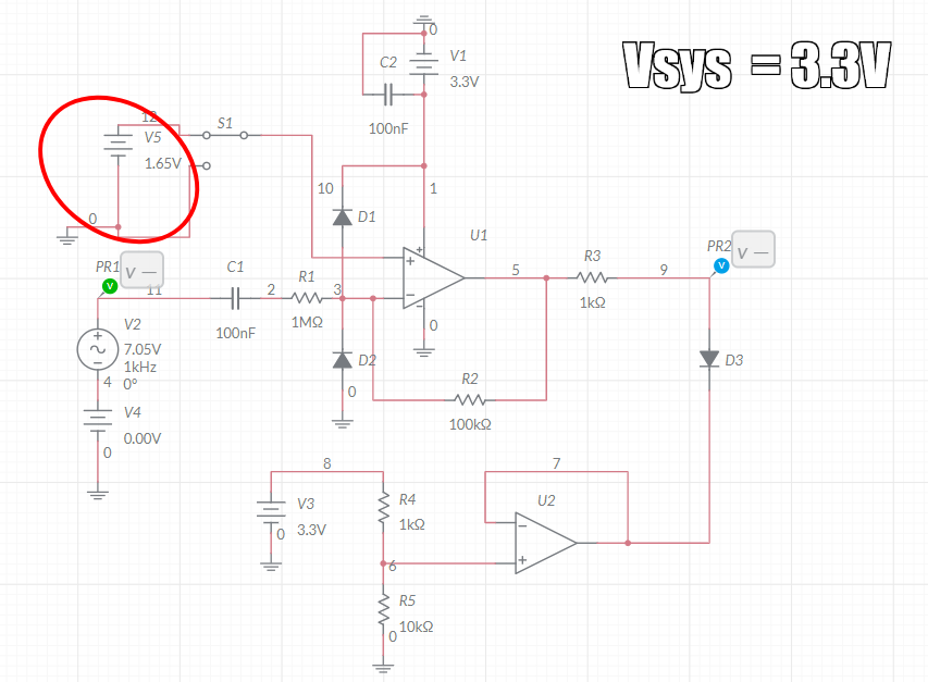
So whatever I apply as Vsys voltage(which is 3.3V here) the input voltage will be shifted to 0V to 3.3V level.
The circled voltage is Vsys/2 that whre the zero voltage of the input voltage will be shifted to on the output so that I can capture both +ve and -ve cycles of the input sine.

Can anyone please explain the working of this circuit? And can I use this make my DIY Oscilloscope?
Thank you in advance.


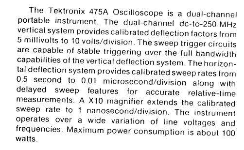 The first of many problems you are going to have is what is the desired bandwidth of your device. Personally, I have a Tektronix 475A which is quoted from the first page "BEFORE OPERATING" (sorry could not copy and paste so here is the png file made with gimp. You will notice that with a magnifier on I have an effective bandwidth of 1 ns/div! I use this often when trying to nail down ringing ie switch contacts, keyboards, etc. Also, most TTL is 5v rail to rail 3v is floating!
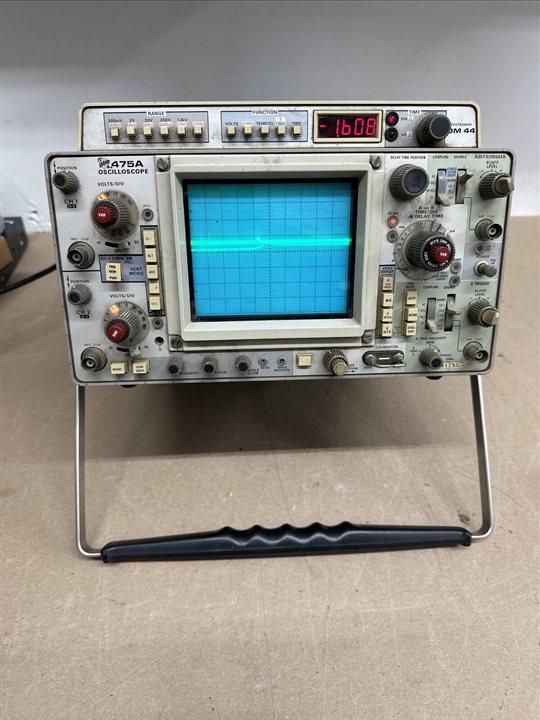 Now don't get me wrong, for a toy it is ok, but save some bucks and sweat. Just buy a good scope. 475 can be found on eBay for ~~ 150 & up with out probes.
