element14 Community
element14 Community
    Register Log In
  • Site
  • Search
  • Log In Register
  • About Us
  • Community Hub
    Community Hub
    • What's New on element14
    • Feedback and Support
    • Benefits of Membership
    • Personal Blogs
    • Members Area
    • Achievement Levels
  • Learn
    Learn
    • Ask an Expert
    • eBooks
    • element14 presents
    • Learning Center
    • Tech Spotlight
    • STEM Academy
    • Webinars, Training and Events
    • Learning Groups
  • Technologies
    Technologies
    • 3D Printing
    • FPGA
    • Industrial Automation
    • Internet of Things
    • Power & Energy
    • Sensors
    • Technology Groups
  • Challenges & Projects
    Challenges & Projects
    • Design Challenges
    • element14 presents Projects
    • Project14
    • Arduino Projects
    • Raspberry Pi Projects
    • Project Groups
  • Products
    Products
    • Arduino
    • Avnet Boards Community
    • Dev Tools
    • Manufacturers
    • Multicomp Pro
    • Product Groups
    • Raspberry Pi
    • RoadTests & Reviews
  • Store
    Store
    • Visit Your Store
    • Choose another store...
      • Europe
      •  Austria (German)
      •  Belgium (Dutch, French)
      •  Bulgaria (Bulgarian)
      •  Czech Republic (Czech)
      •  Denmark (Danish)
      •  Estonia (Estonian)
      •  Finland (Finnish)
      •  France (French)
      •  Germany (German)
      •  Hungary (Hungarian)
      •  Ireland
      •  Israel
      •  Italy (Italian)
      •  Latvia (Latvian)
      •  
      •  Lithuania (Lithuanian)
      •  Netherlands (Dutch)
      •  Norway (Norwegian)
      •  Poland (Polish)
      •  Portugal (Portuguese)
      •  Romania (Romanian)
      •  Russia (Russian)
      •  Slovakia (Slovak)
      •  Slovenia (Slovenian)
      •  Spain (Spanish)
      •  Sweden (Swedish)
      •  Switzerland(German, French)
      •  Turkey (Turkish)
      •  United Kingdom
      • Asia Pacific
      •  Australia
      •  China
      •  Hong Kong
      •  India
      •  Korea (Korean)
      •  Malaysia
      •  New Zealand
      •  Philippines
      •  Singapore
      •  Taiwan
      •  Thailand (Thai)
      • Americas
      •  Brazil (Portuguese)
      •  Canada
      •  Mexico (Spanish)
      •  United States
      Can't find the country/region you're looking for? Visit our export site or find a local distributor.
  • Translate
  • Profile
  • Settings
Experts, Learning and Guidance
  • Technologies
  • More
Experts, Learning and Guidance
Ask an Expert Forum Facing problem in getting proper packets from flir lepton3.5 thermal camera
  • Blog
  • Forum
  • Documents
  • Leaderboard
  • Files
  • Members
  • Mentions
  • Sub-Groups
  • Tags
  • More
  • Cancel
  • New
Join Experts, Learning and Guidance to participate - click to join for free!
Actions
  • Share
  • More
  • Cancel
Forum Thread Details
  • Replies 1 reply
  • Subscribers 283 subscribers
  • Views 867 views
  • Users 0 members are here
  • lepton
  • stm32
  • thermal camera
  • stm32f4discovery
  • flir
Related
See a helpful answer?

Be sure to click 'more' and select 'suggest as answer'!

If you're the thread creator, be sure to click 'more' then 'Verify as Answer'!

Facing problem in getting proper packets from flir lepton3.5 thermal camera

Pushpanjali
Pushpanjali over 2 years ago

We are interfacing FLIR lepton 3.5 thermal camera with STM32f407VET6 to capture thermal image.
In our system, the AGC is disabled by default, we enabled VSYNC using I2C protocol.
Currently the code is reading packet number and printing it on console, our output is in attached image.
The packet number output should be between 1, 2, 3,......60 but it is coming like in image.
Help us to solve this problem.
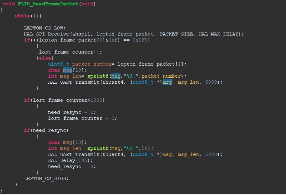
imageimage

#include "main.h"
#include "stdio.h"
#include "string.h"
#include "stdlib.h"
#include "stdbool.h"
#include "LeptonFLiR.h"
#include "i2c.h"
#include "spi.h"
#include "usart.h"
#include "gpio.h"

#define LEPTON_RESET_L_HIGH	HAL_GPIO_WritePin(GPIOC, GPIO_PIN_4, GPIO_PIN_SET)
#define LEPTON_RESET_L_LOW	HAL_GPIO_WritePin(GPIOC, GPIO_PIN_4, GPIO_PIN_RESET)
#define LEPTON_PW_DWN_HIGH	HAL_GPIO_WritePin(GPIOC, GPIO_PIN_5, GPIO_PIN_SET)
#define LEPTON_PW_DWN_LOW	HAL_GPIO_WritePin(GPIOC, GPIO_PIN_5, GPIO_PIN_RESET)
#define LEPTON_CS_HIGH	HAL_GPIO_WritePin(GPIOA, GPIO_PIN_4, GPIO_PIN_SET)
#define LEPTON_CS_LOW	HAL_GPIO_WritePin(GPIOA, GPIO_PIN_4, GPIO_PIN_RESET)

#define PACKET_SIZE    164

LeptonFLiR flirController;
uint8_t lepton_frame_packet[PACKET_SIZE];

int lost_frame_counter = 0;
int frame_complete = 0;
int need_resync = 0;

void SystemClock_Config(void);

void lepton_init(void )
{
	LEPTON_PW_DWN_LOW;
	LEPTON_RESET_L_LOW;
	HAL_Delay(190);
	LEPTON_PW_DWN_HIGH;
	HAL_Delay(190);
	LEPTON_RESET_L_HIGH;
	HAL_Delay(5000);

    flirController.printModuleInfo();
    LEP_RAD_ENABLE_E_TAG mode= flirController.rad_getRadiometryControlEnable();
     char msg[10];
     int msg_len= sprintf(msg,"\n\r %i ",mode);
     HAL_UART_Transmit(&huart4, (uint8_t *)msg, msg_len, 5000);

     flirController.oem_setGPIO_mode(LEP_OEM_GPIO_MODE_VSYNC);
     flirController.oem_getGPIO_mode();
     LEP_SYS_CAM_STATUS_STATES camStatus = flirController.sys_getCameraStatus();
     msg_len= sprintf(msg,"\n\r %i ",camStatus);
     HAL_UART_Transmit(&huart4, (uint8_t *)msg, msg_len, 5000);
     flirController.readInitData();
     HAL_Delay(5000);
}


 void FLIR_ReadFramePacket(void)
{
	 while(1){

	    LEPTON_CS_LOW;
	    HAL_SPI_Receive(&hspi1, lepton_frame_packet, PACKET_SIZE, HAL_MAX_DELAY);
	    if(((lepton_frame_packet[0]&0xF) == 0x0F))
	    	{
	    	 lost_frame_counter++;
	    	}else{
	    		uint8_t packet_number= lepton_frame_packet[1];
	    		char msg[10];
	    		int msg_len= sprintf(msg,"%d ",packet_number);
	    		HAL_UART_Transmit(&huart4, (uint8_t *)msg, msg_len, 5000);
	    	}

	    if(lost_frame_counter>1000)
	    	{
	    		need_resync = 1;
	    		lost_frame_counter = 0;
	    	}
	    if(need_resync)
	    	{
	    		char msg[10];
	    		int msg_len= sprintf(msg,"%d ",58);
	    		HAL_UART_Transmit(&huart4, (uint8_t *)msg, msg_len, 5000);
	    		HAL_Delay(185);
	    		need_resync = 0;
	    	}
	    LEPTON_CS_HIGH;
	 }
}

int main(void)
{
  HAL_Init();
  SystemClock_Config();
  MX_GPIO_Init();
  MX_UART4_Init();
  MX_SPI1_Init();
  MX_I2C1_Init();
  lepton_init();

  while(1){
//	  lepton_getFrameAsync();
	  int vsyn = HAL_GPIO_ReadPin(GPIOB, GPIO_PIN_0);
	  if(vsyn==1){
		  FLIR_ReadFramePacket();
	  }
  	}
  }

void SystemClock_Config(void)
{
  RCC_OscInitTypeDef RCC_OscInitStruct = {0};
  RCC_ClkInitTypeDef RCC_ClkInitStruct = {0};

  __HAL_RCC_PWR_CLK_ENABLE();
  __HAL_PWR_VOLTAGESCALING_CONFIG(PWR_REGULATOR_VOLTAGE_SCALE1);

  /** Initializes the RCC Oscillators according to the specified parameters
  * in the RCC_OscInitTypeDef structure.
  */
  RCC_OscInitStruct.OscillatorType = RCC_OSCILLATORTYPE_HSI;
  RCC_OscInitStruct.HSIState = RCC_HSI_ON;
  RCC_OscInitStruct.HSICalibrationValue = RCC_HSICALIBRATION_DEFAULT;
  RCC_OscInitStruct.PLL.PLLState = RCC_PLL_NONE;
  if (HAL_RCC_OscConfig(&RCC_OscInitStruct) != HAL_OK)
  {
    Error_Handler();
  }

  /** Initializes the CPU, AHB and APB buses clocks
  */
  RCC_ClkInitStruct.ClockType = RCC_CLOCKTYPE_HCLK|RCC_CLOCKTYPE_SYSCLK
                              |RCC_CLOCKTYPE_PCLK1|RCC_CLOCKTYPE_PCLK2;
  RCC_ClkInitStruct.SYSCLKSource = RCC_SYSCLKSOURCE_HSI;
  RCC_ClkInitStruct.AHBCLKDivider = RCC_SYSCLK_DIV1;
  RCC_ClkInitStruct.APB1CLKDivider = RCC_HCLK_DIV1;
  RCC_ClkInitStruct.APB2CLKDivider = RCC_HCLK_DIV1;

  if (HAL_RCC_ClockConfig(&RCC_ClkInitStruct, FLASH_LATENCY_0) != HAL_OK)
  {
    Error_Handler();
  }
}

void Error_Handler(void)
{
  /* USER CODE BEGIN Error_Handler_Debug */
  /* User can add his own implementation to report the HAL error return state */
  __disable_irq();
  while (1)
  {
	  char msg[10];
	  int msg_len= sprintf(msg,"%i ",7);
	  HAL_UART_Transmit(&huart4, (uint8_t *)msg, msg_len, 5000);
	  HAL_Delay(5000);
  }
  /* USER CODE END Error_Handler_Debug */
}

  • Sign in to reply
  • Cancel

Top Replies

  • shabaz
    shabaz over 2 years ago +3
    Hi, Why not just simply visually check the image you're assembling. If it looks wrong, then you're missing data (i.e. perhaps you are not reading the packets as quickly as you're supposed to be). For…
Parents
  • shabaz
    shabaz over 2 years ago

    Hi,

    Why not just simply visually check the image you're assembling. If it looks wrong, then you're missing data (i.e. perhaps you are not reading the packets as quickly as you're supposed to be). For instance, perhaps the UART transmits are causing delays (I have no idea).

    Furthermore, it would be a good idea to dump out several of the first bytes of each packet, to confirm they are what you expect, because you're printing large values like 120 and 145 occasionally, and they are not what you say you're expecting to see.

    Write a proper function that you can use for debugging the SPI data as it arrives, i.e. dump out as hex bytes in a decent format. Of course, you may not be able to dump out every packet in real-time, but you can certainly do that for one packet, to examine it, and then change the code to dump out the second packet (as an example) until you spot what's going wrong.

    I have actually used this module, but many years ago, so I can't recall the detail, but I certainly remember part of the debugging was achieved by simply looking at the image.

    Also, are you sure you've got good appropriate hardware. The SPI interface runs at a very high speed, and it may be worth probing with an oscilloscope to confirm it's as expected (the correct amplitude for instance! - check the levels are supported by your microcontroller, by reading the microcontroller datasheet electrical specifications).  If it's not, then it's no surprise to read unexpected content.

    • Cancel
    • Vote Up +3 Vote Down
    • Sign in to reply
    • Cancel
Reply
  • shabaz
    shabaz over 2 years ago

    Hi,

    Why not just simply visually check the image you're assembling. If it looks wrong, then you're missing data (i.e. perhaps you are not reading the packets as quickly as you're supposed to be). For instance, perhaps the UART transmits are causing delays (I have no idea).

    Furthermore, it would be a good idea to dump out several of the first bytes of each packet, to confirm they are what you expect, because you're printing large values like 120 and 145 occasionally, and they are not what you say you're expecting to see.

    Write a proper function that you can use for debugging the SPI data as it arrives, i.e. dump out as hex bytes in a decent format. Of course, you may not be able to dump out every packet in real-time, but you can certainly do that for one packet, to examine it, and then change the code to dump out the second packet (as an example) until you spot what's going wrong.

    I have actually used this module, but many years ago, so I can't recall the detail, but I certainly remember part of the debugging was achieved by simply looking at the image.

    Also, are you sure you've got good appropriate hardware. The SPI interface runs at a very high speed, and it may be worth probing with an oscilloscope to confirm it's as expected (the correct amplitude for instance! - check the levels are supported by your microcontroller, by reading the microcontroller datasheet electrical specifications).  If it's not, then it's no surprise to read unexpected content.

    • Cancel
    • Vote Up +3 Vote Down
    • Sign in to reply
    • Cancel
Children
No Data
element14 Community

element14 is the first online community specifically for engineers. Connect with your peers and get expert answers to your questions.

  • Members
  • Learn
  • Technologies
  • Challenges & Projects
  • Products
  • Store
  • About Us
  • Feedback & Support
  • FAQs
  • Terms of Use
  • Privacy Policy
  • Legal and Copyright Notices
  • Sitemap
  • Cookies

An Avnet Company © 2025 Premier Farnell Limited. All Rights Reserved.

Premier Farnell Ltd, registered in England and Wales (no 00876412), registered office: Farnell House, Forge Lane, Leeds LS12 2NE.

ICP 备案号 10220084.

Follow element14

  • X
  • Facebook
  • linkedin
  • YouTube