Im working on stm32f4 series microcontroller.
I'm trying to read mpu9250 three sensors(accelerometer,gyroscope ,magnetometer) data from fifo buffer. I'm not able to read magnetormeter data from FIFO buffer Because I may have made errors on the I2C master and slave(slave 0) configuration. I have attached the code. I require help in resolving this.
void mpu9250_init()
{
HAL_StatusTypeDef ret = HAL_I2C_IsDeviceReady(&hi2c1,0x68<<1,1,100);
// REG 107 PWR_MGMT_1 wake up
//SLEEP When set to 0, this bit puts the MPU out of sleep mode.0x6b
uint8_t data = 0x00;
ret = HAL_I2C_Mem_Write(&hi2c1, 0x68<<1,107,1,&data,1,100);
HAL_Delay(100);
//register 27 or 0x1b,GYRO_FS_SEL configure gyro sensitivity full scale range
data = 0x10; // +/- 1000 degree/sec 32.8
ret = HAL_I2C_Mem_Write(&hi2c1, 0x68<<1, 27, 1,&data,1,100);
HAL_Delay(100);
//register 28 or 0x1c,ACCEL_FS_SEL configure ACCEL_CONFIG
data = 0x10; // +/- 8g 4,096
ret = HAL_I2C_Mem_Write(&hi2c1, 0x68<<1, 28, 1,&data,1,100);
HAL_Delay(100);
data = 0x01; // DLPF (184HZ BW gyroscope) results in 1000hz output
ret = HAL_I2C_Mem_Write(&hi2c1,0x68<<1,26, 1,&data,1,100);
HAL_Delay(100);
data = 0x01; // DLPF (ACC CONFIG2 218.1 BW)
ret = HAL_I2C_Mem_Write(&hi2c1, 0x68<<1,29 , 1,&data,1,100);
HAL_Delay(100);
data = 0x04; // sample rate divider
ret = HAL_I2C_Mem_Write(&hi2c1, 0x68<<1, 25, 1,&data,1,100);
HAL_Delay(100);
//Magnetometer I2C Master
//uint8_t temp6_data = 0X02; // Set bypass mode for the magnetometer.(im not using this bcoz i want to do with i2c master)
//ret = HAL_I2C_Mem_Write(&hi2c1,0x68<<1,55,1,&temp6_data,1,100);
//HAL_Delay(200);
//( PWR_MGMNT_1, CLOCK_SEL_PLL )
data = 0x01;
ret = HAL_I2C_Mem_Write(&hi2c1, 0x68<<1,107, 1,&data,1,100);
HAL_Delay(100);
//( USER_CTRL, I2C_MST_EN )
//Enable I2C Master Mode
data = 0b0010000;//(bit 5)
HAL_I2C_Mem_Write(&hi2c1, 0x68 << 1,106, 1, &data, 1,100);
HAL_Delay(100);
//( I2C_MST_CTRL,I2C_MST_CLK )
//set the I2C bus speed to 400 kHz ,set 13 = D
data = 0x0D; // Enable I2C Master reg 36 I2C_MST_CTRL (0X24)
HAL_I2C_Mem_Write(&hi2c1, 0x68 << 1,36, 1, &data, 1,100);
HAL_Delay(200);
//Configure i2c slave register
//Set SLV0 to read from AK8963
// AK8963_ADDR; // Set I2C address of magnetometer // REG 43(0X2B) I2C_SLV0_ADDR
data = 0x8C;//0b10001100
ret = HAL_I2C_Mem_Write(&hi2c1, 0x68 << 1,37, 1, &data, 1,100);
HAL_Delay(100);
//Configure the I2C Master to access magnetometer data
data = 0X03; //Set Slave 0 to read from AK8963 //I2C_SLV0_REG
ret = HAL_I2C_Mem_Write(&hi2c1, 0x68 << 1,38, 1, &data, 1,100);
HAL_Delay(100);
//Set the number of bytes to read from AK8963
data = 0x88; // 8 bytes of data from magnetometer // I2C_SLV0_CTRL 1000 1000
ret = HAL_I2C_Mem_Write(&hi2c1, 0x68 << 1,39, 1, &data, 1,100);
HAL_Delay(100);
//AK8963(magnetometer) init
//(AK8963_CNTL1,AK8963_PWR_DOWN)
data = 0x00; //power down the magnetometer (CNTL1)
ret = HAL_I2C_Mem_Write(&hi2c1,0x0C<<1,0x0A,1,&data,1,100);
// Set 16-bits output & fuse ROM access mode
data = 0x0F;
ret = HAL_I2C_Mem_Write(&hi2c1,0x0C<<1,0x0A,1,&data,1,100);
//power down the magnetometer (CNTL1)
data = 0x00;
ret = HAL_I2C_Mem_Write(&hi2c1,0x0C<<1,0x0A,1,&data,1,100);
//reset magnetometer
data = 0x01;// CONTROL 2 (0 NORMAL OR 1 RESET)
ret = HAL_I2C_Mem_Write(&hi2c1,0x0C<<1,0x0B,1,&data,1,100);
// Request continuous magnetometer measurements
data = 0x06;
ret = HAL_I2C_Mem_Write(&hi2c1,0x0C<<1,0x0A,1,&data,1,100);
//Enable fifo for Accelerometer,Magnetometer,Gyroscope
// set fifo en (bit 6) in USER_CTRL REG (0X6A)
data = 0b01100000;//40 fifo enable //bit 5 for i2c master enable
ret = HAL_I2C_Mem_Write(&hi2c1,0x68<<1,106,1,&data,1,100);
HAL_Delay(100);
data = 0b01000000;//bit 6 set to 1 (no overwrite)
ret = HAL_I2C_Mem_Write(&hi2c1,0x68<<1,26,1,&data,1,100);
HAL_Delay(100);
//Enable fifo for gyro and acc and mag - in REG 35 set 0b01111100 0x78
data = 0b01111001;//
ret = HAL_I2C_Mem_Write(&hi2c1,0x68<<1,35,1,&data,1,100);
HAL_Delay(100);
}
//Registers 59 to 64 – Accelerometer Measurements
//Registers 0X03 to 0x08 - Magnetometer Measurements
//Registers 67 to 72 – Gyroscope Measurements
uint8_t data_acc[6]={};
uint8_t data_gyro[6]={};
uint8_t data_mag[6]={};
uint8_t fifo_count[2];
uint16_t fifo_size;
uint8_t fifo_data[23];
uint16_t length = sizeof(fifo_data);
#define MPU9250_ADD_WRITE 0x68<<1
#define MPU9250_ADD_READ ((MPU9250_ADD_WRITE)|(0x01))
void mpu9250_read()
{
//FIFO_COUNTH 114 ,FIFO_COUNTL 115,FIFO_R_W 116
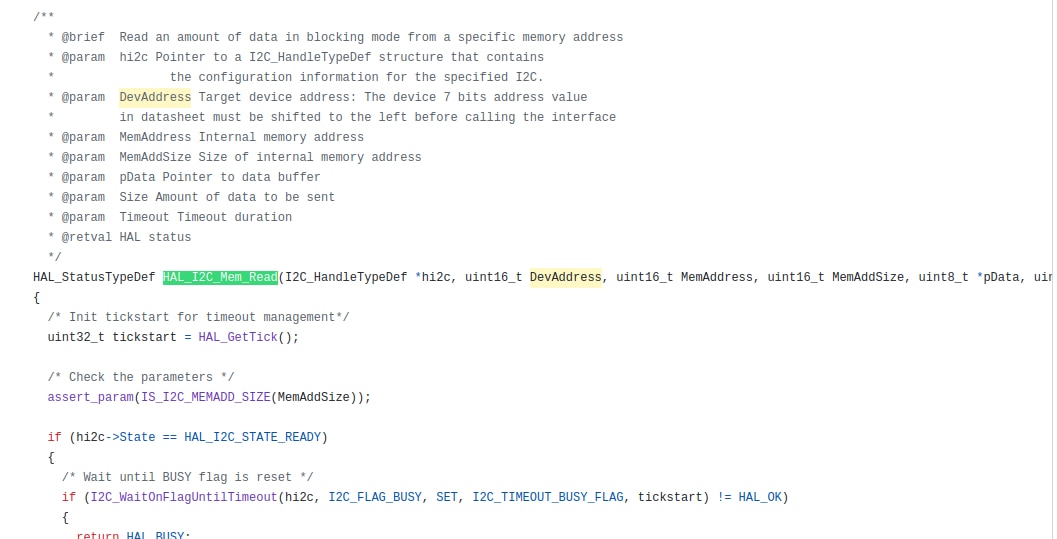
HAL_StatusTypeDef ret1 = HAL_I2C_Mem_Read(&hi2c1,MPU9250_ADD_READ,114,1,&fifo_count[0],6,100);
ret1 = HAL_I2C_Mem_Read(&hi2c1,MPU9250_ADD_READ,115,1,&fifo_count[1],6,100);
fifo_size = (fifo_count[0]<<8)|fifo_count[1];
if (fifo_size < length)
{
length = fifo_size;
}
ret1 = HAL_I2C_Mem_Read(&hi2c1,0x68<<1|0x01,116,1,fifo_data,length,100);
//return fifo_data[0];
x_acc = (uint16_t)fifo_data[0]<<8|fifo_data[1];
y_acc = (uint16_t)fifo_data[2]<<8|fifo_data[3];
z_acc = (uint16_t)fifo_data[4]<<8|fifo_data[5];
x_gyro = (uint16_t)fifo_data[6]<<8|fifo_data[7];
y_gyro = (uint16_t)fifo_data[8]<<8|fifo_data[9];
z_gyro = (uint16_t)fifo_data[10]<<8|fifo_data[11];
x_mag = (uint16_t)fifo_data[12]<<8|fifo_data[13];
y_mag = (uint16_t)fifo_data[14]<<8|fifo_data[15];
z_mag = (uint16_t)fifo_data[16]<<8|fifo_data[17];
}