element14 Community
element14 Community
    Register Log In
  • Site
  • Search
  • Log In Register
  • Community Hub
    Community Hub
    • What's New on element14
    • Feedback and Support
    • Benefits of Membership
    • Personal Blogs
    • Members Area
    • Achievement Levels
  • Learn
    Learn
    • Ask an Expert
    • eBooks
    • element14 presents
    • Learning Center
    • Tech Spotlight
    • STEM Academy
    • Webinars, Training and Events
    • Learning Groups
  • Technologies
    Technologies
    • 3D Printing
    • FPGA
    • Industrial Automation
    • Internet of Things
    • Power & Energy
    • Sensors
    • Technology Groups
  • Challenges & Projects
    Challenges & Projects
    • Design Challenges
    • element14 presents Projects
    • Project14
    • Arduino Projects
    • Raspberry Pi Projects
    • Project Groups
  • Products
    Products
    • Arduino
    • Avnet & Tria Boards Community
    • Dev Tools
    • Manufacturers
    • Multicomp Pro
    • Product Groups
    • Raspberry Pi
    • RoadTests & Reviews
  • About Us
    About the element14 Community
  • Store
    Store
    • Visit Your Store
    • Choose another store...
      • Europe
      •  Austria (German)
      •  Belgium (Dutch, French)
      •  Bulgaria (Bulgarian)
      •  Czech Republic (Czech)
      •  Denmark (Danish)
      •  Estonia (Estonian)
      •  Finland (Finnish)
      •  France (French)
      •  Germany (German)
      •  Hungary (Hungarian)
      •  Ireland
      •  Israel
      •  Italy (Italian)
      •  Latvia (Latvian)
      •  
      •  Lithuania (Lithuanian)
      •  Netherlands (Dutch)
      •  Norway (Norwegian)
      •  Poland (Polish)
      •  Portugal (Portuguese)
      •  Romania (Romanian)
      •  Russia (Russian)
      •  Slovakia (Slovak)
      •  Slovenia (Slovenian)
      •  Spain (Spanish)
      •  Sweden (Swedish)
      •  Switzerland(German, French)
      •  Turkey (Turkish)
      •  United Kingdom
      • Asia Pacific
      •  Australia
      •  China
      •  Hong Kong
      •  India
      •  Japan
      •  Korea (Korean)
      •  Malaysia
      •  New Zealand
      •  Philippines
      •  Singapore
      •  Taiwan
      •  Thailand (Thai)
      •  Vietnam
      • Americas
      •  Brazil (Portuguese)
      •  Canada
      •  Mexico (Spanish)
      •  United States
      Can't find the country/region you're looking for? Visit our export site or find a local distributor.
  • Translate
  • Profile
  • Settings
Experts, Learning and Guidance
  • Technologies
  • More
Experts, Learning and Guidance
Ask an Expert Forum making a circuit board for IDE to USB converter
  • Blog
  • Forum
  • Documents
  • Leaderboard
  • Files
  • Members
  • Mentions
  • Sub-Groups
  • Tags
  • More
  • Cancel
  • New
Join Experts, Learning and Guidance to participate - click to join for free!
Actions
  • Share
  • More
  • Cancel
Forum Thread Details
  • State Suggested Answer
  • Replies 8 replies
  • Answers 1 answer
  • Subscribers 322 subscribers
  • Views 324 views
  • Users 0 members are here
  • ide
  • harddisk
  • usb
  • data
  • ask_the_expert
  • hardware_interfacing
Related
See a helpful answer?

Be sure to click 'more' and select 'suggest as answer'!

If you're the thread creator, be sure to click 'more' then 'Verify as Answer'!

making a circuit board for IDE to USB converter

safia_fatima
safia_fatima 12 days ago

Hi

I am trying to make an external hard drive casing for an IDE HDD. The hard drive should connect to the laptop using a USB cable. The power comes from a molex connector in the IDE drive which is interfaced with a serial port for the power supply adapter. I need the schematic for this and step by step process on how to build it on a perf board, for example. I have an existing converter but it seems to have a short circuit and I cannot trace the problem. The market has a number of converters, but I would prefer to build one to learn how the circuit works. Please kindly guide me on the best way to connect the hard disk.

  • Sign in to reply
  • Cancel

Top Replies

  • safia_fatima
    safia_fatima 8 days ago in reply to vmate +1
    The board I have is a PCB (I know vector board will be too busy when built from scratch and takes lot of effort. I checked the TI data sheet and its a work of art. I didn't intend to work on the micro…
  • vmate
    0 vmate 12 days ago

    You won't be able to make this on a perfboard, there's simply no way to properly route 20+ signals. The bare minimum you'd need is a 2 layer PCB, but 4 would almost certainly be preferred. This is not a good project to learn at all, you will spend a lot of money and never get it working, or end up frustrated.

    Some ICs which have good documentation are the TI TUSB6250 and CY7C68300B. However, they are both obsolete, so obtaining them will be a challenge. Still, you should look at the datasheets, to see what you're up against.

    Also, I don't quite understand your power supply setup and serial ports part. You'll need an external 12V power supply to power the drive, and ideally create 5V from that as well, instead of trying to draw 1-2A from USB. 

    • Cancel
    • Vote Up 0 Vote Down
    • Sign in to reply
    • Verify Answer
    • Reject Answer
    • Cancel
  • safia_fatima
    0 safia_fatima 12 days ago in reply to vmate

    I will check the documentation. Thank you very much for your reply.

    I understand, the technology is obsolete. It is a 3.5 inch hard drive with IDE interface and 4 pin power connector that originally connected to the old motherboard of a PC. I need to now interface the IDE to USB so that I can connect it to a laptop and recover the data. I was trying to figure out if it is possible to trace the short circuit with the existing board of the external hard drive casing I have. 

    • Cancel
    • Vote Up 0 Vote Down
    • Sign in to reply
    • Verify Answer
    • Cancel
  • geralds
    0 geralds 12 days ago in reply to safia_fatima

    try this: USB-IDE converter at amazon

    https://www.amazon.com/s?k=usb+ide+converter&__mk_de_DE=%C3%85M%C3%85%C5%BD%C3%95%C3%91&crid=OOHXRMUCXGZK&sprefix=usb+ide+converter%2Caps%2C221&ref=nb_sb_noss_1

    • Cancel
    • Vote Up 0 Vote Down
    • Sign in to reply
    • Verify Answer
    • Cancel
  • safia_fatima
    0 safia_fatima 11 days ago in reply to geralds

    Thank you for the link.

    • Cancel
    • Vote Up 0 Vote Down
    • Sign in to reply
    • Verify Answer
    • Cancel
  • phoenixcomm
    0 phoenixcomm 10 days ago in reply to vmate

    I thought I was the harsh one..  you have now been elected to the team..

    but 20+ signals aren't that bad you could use a Vector board with a 22/44 connector on it. I have played with a lot more wire than  that.. I like you buy dont build it suggestion. power is trivial a small PC power supply..  or one 12v wall rat and peel of the 5 with a 3 lead Regulator. Tah Dah. 

    enjoy ~~ Cris H.

    • Cancel
    • Vote Up 0 Vote Down
    • Sign in to reply
    • Verify Answer
    • Cancel
  • safia_fatima
    0 safia_fatima 9 days ago in reply to phoenixcomm

    Thank you for your reply.

    • Cancel
    • Vote Up 0 Vote Down
    • Sign in to reply
    • Verify Answer
    • Cancel
  • vmate
    0 vmate 9 days ago in reply to phoenixcomm

    Well, if you tried, you probably could do it, but routing 20 signals for a parallel bus at 66MHz on a perfboard is the type of thing you do because you want to challenge yourself, not because you need it to work.

    My point was just that this is not the sort of project you want to get started with, to get into electronics. I wouldn't attempt this myself, because it's pure pain and suffering, with zero upsides.

    • Cancel
    • Vote Up 0 Vote Down
    • Sign in to reply
    • Verify Answer
    • Cancel
  • safia_fatima
    0 safia_fatima 8 days ago in reply to vmate

    The board I have is a PCB (I know vector board will be too busy when built from scratch and takes lot of effort. I checked the TI data sheet and its a work of art. I didn't intend to work on the micro controller, just put the parts together, if possible).

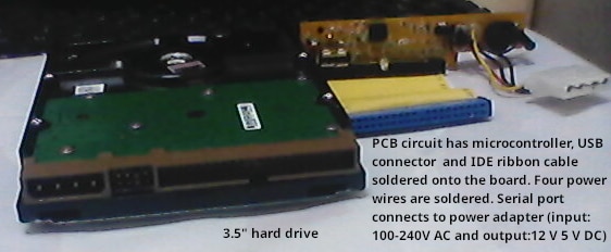
    Attached is the image of the PCB and hard drive. On connecting to power source and pushing switch ON, LED glowed only once and HDD did not spin. I cleaned the extra solder and debris of the PCB with rubbing alcohol and I did the continuity test using multi meter for all PCB components. The LED started glowing and the HDD started to spin.

    There is a USB Type A female connector on the PCB. The cable has USB type A male connectors on both sides, one end for the PCB USB connector and the other for laptop USB connector. The HDD does not come up in the list of disk drives on the laptop. Any other tests I can possibly do to identify the problem?

    image

    • Cancel
    • Vote Up +1 Vote Down
    • Sign in to reply
    • Verify Answer
    • Cancel
element14 Community

element14 is the first online community specifically for engineers. Connect with your peers and get expert answers to your questions.

  • Members
  • Learn
  • Technologies
  • Challenges & Projects
  • Products
  • Store
  • About Us
  • Feedback & Support
  • FAQs
  • Terms of Use
  • Privacy Policy
  • Legal and Copyright Notices
  • Sitemap
  • Cookies

An Avnet Company © 2026 Premier Farnell Limited. All Rights Reserved.

Premier Farnell Ltd, registered in England and Wales (no 00876412), registered office: Farnell House, Forge Lane, Leeds LS12 2NE.

ICP 备案号 10220084.

Follow element14

  • X
  • Facebook
  • linkedin
  • YouTube