element14 Community
element14 Community
    Register Log In
  • Site
  • Search
  • Log In Register
  • About Us
  • Community Hub
    Community Hub
    • What's New on element14
    • Feedback and Support
    • Benefits of Membership
    • Personal Blogs
    • Members Area
    • Achievement Levels
  • Learn
    Learn
    • Ask an Expert
    • eBooks
    • element14 presents
    • Learning Center
    • Tech Spotlight
    • STEM Academy
    • Webinars, Training and Events
    • Learning Groups
  • Technologies
    Technologies
    • 3D Printing
    • FPGA
    • Industrial Automation
    • Internet of Things
    • Power & Energy
    • Sensors
    • Technology Groups
  • Challenges & Projects
    Challenges & Projects
    • Design Challenges
    • element14 presents Projects
    • Project14
    • Arduino Projects
    • Raspberry Pi Projects
    • Project Groups
  • Products
    Products
    • Arduino
    • Avnet Boards Community
    • Dev Tools
    • Manufacturers
    • Multicomp Pro
    • Product Groups
    • Raspberry Pi
    • RoadTests & Reviews
  • Store
    Store
    • Visit Your Store
    • Choose another store...
      • Europe
      •  Austria (German)
      •  Belgium (Dutch, French)
      •  Bulgaria (Bulgarian)
      •  Czech Republic (Czech)
      •  Denmark (Danish)
      •  Estonia (Estonian)
      •  Finland (Finnish)
      •  France (French)
      •  Germany (German)
      •  Hungary (Hungarian)
      •  Ireland
      •  Israel
      •  Italy (Italian)
      •  Latvia (Latvian)
      •  
      •  Lithuania (Lithuanian)
      •  Netherlands (Dutch)
      •  Norway (Norwegian)
      •  Poland (Polish)
      •  Portugal (Portuguese)
      •  Romania (Romanian)
      •  Russia (Russian)
      •  Slovakia (Slovak)
      •  Slovenia (Slovenian)
      •  Spain (Spanish)
      •  Sweden (Swedish)
      •  Switzerland(German, French)
      •  Turkey (Turkish)
      •  United Kingdom
      • Asia Pacific
      •  Australia
      •  China
      •  Hong Kong
      •  India
      •  Korea (Korean)
      •  Malaysia
      •  New Zealand
      •  Philippines
      •  Singapore
      •  Taiwan
      •  Thailand (Thai)
      • Americas
      •  Brazil (Portuguese)
      •  Canada
      •  Mexico (Spanish)
      •  United States
      Can't find the country/region you're looking for? Visit our export site or find a local distributor.
  • Translate
  • Profile
  • Settings
Experts, Learning and Guidance
  • Technologies
  • More
Experts, Learning and Guidance
Ask an Expert Forum How to Calculate Filter Capacitor Value? (and A Few Other Questions)
  • Blog
  • Forum
  • Documents
  • Leaderboard
  • Files
  • Members
  • Mentions
  • Sub-Groups
  • Tags
  • More
  • Cancel
  • New
Join Experts, Learning and Guidance to participate - click to join for free!
Actions
  • Share
  • More
  • Cancel
Forum Thread Details
  • Replies 4 replies
  • Subscribers 290 subscribers
  • Views 2967 views
  • Users 0 members are here
Related
See a helpful answer?

Be sure to click 'more' and select 'suggest as answer'!

If you're the thread creator, be sure to click 'more' then 'Verify as Answer'!

How to Calculate Filter Capacitor Value? (and A Few Other Questions)

swankybarbecue4
swankybarbecue4 over 7 years ago

Hello,


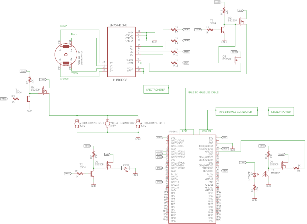
I am powering and controlling a few small coin vibration motors, a stepper-motor controller, and a stepper-motor with a Raspberry Pi Zero (schematic attached and shown below). I have a lot of questions; please bear with me! image


jw0752, You have given me great answers in the past, so I trust you the most! image


1. How would you calculate the value of a filter capacitor for a DC motor? In my case, I want to filter the noise coming from the small vibration motors, but I would like to know mathematically, not just a rule of thumb, so I can calculate values properly for future projects.

     a. Would you ever put two capacitors in parallel for any reason (i.e. for redundancy of some sort)?

     b. I have found by tearing apart products (especially small RC cars) over the years that a 0.1uF ceramic capacitor in parallel will do the trick to filter the noise coming from small DC motors. Would this be a good rule-of-thumb to follow for quick applications?

     c. Do brush-less motors need filtering capacitors? (i.e.does the same calculate/rule-of-thumb apply to both motors with brushes and motors without brushes?)

     d. Since these vibration motors are so small, would I need a filtering capacitor for my application?

     e. Do stepper-motors need filtering capacitors?

          i. Since my stepper-motor is so small, would I need filtering capacitor(s) for my application?

          ii. I have read online that you would place your filtering capacitor close to the input of your stepper-motor driver; I assumed that you would place a non-polarized capacitor across each stepper-motor coil. Where should I place my capacitor(s)? 

          iii. Do I need capacitors for both the input and outputs of my stepper motor driver?

2. Also, is it okay to connect the gates of two MOSFETS to the same gate-controlling circuit(shown in the upper-right corner of the schematic I need to control pins VCC1 and VCC2 with 5V and pins 1,2EN and 3,4EN with 3.3V simultaneously(these pins are located on the  SN754410NESN754410NE stepper-motor driver IC

3. Last thing, I want to create a simple circuit that will send a high logic level of 3.3V to a GPIO pin on the Raspberry Pi when current flows across the vibration motors. This circuit will be used to let the Raspberry Pi know if the vibration motors are spinning successfully or not. The dilemma I have run into is if a motor were to fail and therefore not spin, would the same amount of current flow across the non-spinning motor and give a false reading to the Pi, indicating that the motor is spinning? (This brings me to my questions below)

     a. Would the amount of current flowing thought a DC motor change if the rotor is rotating or not? (i.e. current flowing with the rotor freely spinning vs the rotor stuck in place)

     b. Would the amount of current flowing thought a DC motor under normal operation be identical to the amount of current flowing through the motor if the motor were to break internally and cause a direct short? (i.e. current flowing through motor under normal operation vs broken motor with internal direct short)

          i. Would it make a difference if the DC motor is brush-less or not?

image

Attachments:
image
  • Sign in to reply
  • Cancel

Top Replies

  • jw0752
    jw0752 over 7 years ago +7
    Hi Merrick, Thank you for your vote of confidence. I have been on the road and haven't had a chance to see your question until now. It looks to me like three-phase and dougw have given you better advice…
  • Robert Peter Oakes
    Robert Peter Oakes over 7 years ago +6
    For the stepper motor, DO NOT put caps or any other component across the motor winding, it will mess up the current management of the controller, DO put a good bulk capacitor and a filter capacitor across…
  • dougw
    dougw over 7 years ago +5
    1a Capacitors in parallel add up as three-phase points out. This is sometimes done to increase capacitance and sometimes because different capacitor technologies have different strengths- some are good…
  • three-phase
    three-phase over 7 years ago

    This document may provide you with some of the answers to your questions regarding the motor suppression


    DC Motor EMI Suppression


    Capacitors placed in parallel change the value of the capacitance to the sum of the capacitors, so whilst it may give an element of redundancy, it isn't 100% effective. Multiple capacitors are usually used to get the capacitor as close as possible to the source of the noise to improve the effect of them.


    The amount of current flowing to a DC motor with a locked rotor is the same as the initial start-up current which will be the voltage applied divided by the circuit resistance. The same would apply if the motor developed an internal short circuit, i.e the voltage applied divided by the resistance of the short. When the motor is spinning under normal operation, the current flowing will be proportional to the power the motor has to provide.


    DC Motor Starting Presentation


    Kind regards

    • Cancel
    • Vote Up +4 Vote Down
    • Sign in to reply
    • Cancel
  • dougw
    dougw over 7 years ago

    1a Capacitors in parallel add up as three-phase points out. This is sometimes done to increase capacitance and sometimes because different capacitor technologies have different strengths- some are good against fast noise and some are good against large transients.

    1b .1uf is good against hf noise but not large transients

    1c brushless motors may need more filtering than commutating motors - it depends on construction and design

    1d if the motors are running from the same power supply as the computer, filtering is a good idea

    1e all motors draw significant current at various times and they can affect the power supply if they are not filtered adequately

    1eii filtering as close as possible to the source of the noise is better as it provides less opportunity for the noise to couple into other circuits

    1eiii capacitors should be on the power supplies - putting them on the driver circuits can stress the drivers - it may help with noise, but you need to calculate if it is feasible

    2 you can connect two gates together as long as whatever is driving them can handle the extra gate capacitance. A small resistor to limit drive current may be needed to protect the driver. The extra gate capacitance can also slow down switching speeds if that is important.

    3 DC motors draw more current when they are stalled than when they are running. Detecting high current is a way to detect a stalled motor. An internal short will draw at least as much current as a stalled motor and maybe more.

    If the circuit fails open the current goes to zero.

    A brushless motor may be less likely to see excessive current in a failure, but it depends on the failure mode and brushless motors have more components that might fail.

    • Cancel
    • Vote Up +5 Vote Down
    • Sign in to reply
    • Cancel
  • jw0752
    jw0752 over 7 years ago

    Hi Merrick,

    Thank you for your vote of confidence. I have been on the road and haven't had a chance to see your question until now. It looks to me like three-phase  and dougw  have given you better advice than I would have been able to do. You asked about calculating a proper capacitance in the first part of your question. While this may be possible if you had all the data about your motors a more practical approach would be to Pick a capacitance as suggested by Doug and then look at the line with a scope. You could experiment with a few different capacitances to see if one value worked better than the others. I am not an expert so this would be my approach. I will monitor this stream to see if I can be of any help and also to learn what I can from your excellent questions.

    John

    • Cancel
    • Vote Up +7 Vote Down
    • Sign in to reply
    • Cancel
  • Robert Peter Oakes
    Robert Peter Oakes over 7 years ago

    For the stepper motor, DO NOT put caps or any other component across the motor winding, it will mess up the current management of the controller, DO put a good bulk capacitor and a filter capacitor across the supply as close to the supply pins of the controller as you can, this will minimize noise back feeding in the supply and allow better torque in the motors as the supply will not be dipping so much as the state changes,


    This brings us to capacitors in parallel. Yes it is a common practice to do this as Capacitors and Inductors are frequency dependent (A capacitor  has inductor qualities at certain frequency;s as there often made by winding foil)


    So if you want bulk local to a chip decoupling and also also higher frequency noise suppression then two capacitors in parallel will do a job better, for instance a 10uF for bulk capacity and lower frequency filtering, and a 0.1uF in parallel to provide higher frequency noise suppression


    For your vibration motors, a DIODE across the coils to suppress back emf and a bulk + filter cap on the supply rail close to the switching transistor


    For detecting stalled conditions / shorts etc, many of the controllers available have this built into them, I suggest you use this


    For BRUSHED motors (Steppers are not brushed), you will find alot of EMI caused by the brushes sliding between winding and this is often suppressed with low value filter caps across the coil (100nF or so), make sure they have a high voltage rating, you will be surprised how high a voltage is produced when a coil is de-energized.

    • Cancel
    • Vote Up +6 Vote Down
    • Sign in to reply
    • Cancel
element14 Community

element14 is the first online community specifically for engineers. Connect with your peers and get expert answers to your questions.

  • Members
  • Learn
  • Technologies
  • Challenges & Projects
  • Products
  • Store
  • About Us
  • Feedback & Support
  • FAQs
  • Terms of Use
  • Privacy Policy
  • Legal and Copyright Notices
  • Sitemap
  • Cookies

An Avnet Company © 2025 Premier Farnell Limited. All Rights Reserved.

Premier Farnell Ltd, registered in England and Wales (no 00876412), registered office: Farnell House, Forge Lane, Leeds LS12 2NE.

ICP 备案号 10220084.

Follow element14

  • X
  • Facebook
  • linkedin
  • YouTube