element14 Community
element14 Community
    Register Log In
  • Site
  • Search
  • Log In Register
  • Community Hub
    Community Hub
    • What's New on element14
    • Feedback and Support
    • Benefits of Membership
    • Personal Blogs
    • Members Area
    • Achievement Levels
  • Learn
    Learn
    • Ask an Expert
    • eBooks
    • element14 presents
    • Learning Center
    • Tech Spotlight
    • STEM Academy
    • Webinars, Training and Events
    • Learning Groups
  • Technologies
    Technologies
    • 3D Printing
    • FPGA
    • Industrial Automation
    • Internet of Things
    • Power & Energy
    • Sensors
    • Technology Groups
  • Challenges & Projects
    Challenges & Projects
    • Design Challenges
    • element14 presents Projects
    • Project14
    • Arduino Projects
    • Raspberry Pi Projects
    • Project Groups
  • Products
    Products
    • Arduino
    • Avnet & Tria Boards Community
    • Dev Tools
    • Manufacturers
    • Multicomp Pro
    • Product Groups
    • Raspberry Pi
    • RoadTests & Reviews
  • About Us
  • Store
    Store
    • Visit Your Store
    • Choose another store...
      • Europe
      •  Austria (German)
      •  Belgium (Dutch, French)
      •  Bulgaria (Bulgarian)
      •  Czech Republic (Czech)
      •  Denmark (Danish)
      •  Estonia (Estonian)
      •  Finland (Finnish)
      •  France (French)
      •  Germany (German)
      •  Hungary (Hungarian)
      •  Ireland
      •  Israel
      •  Italy (Italian)
      •  Latvia (Latvian)
      •  
      •  Lithuania (Lithuanian)
      •  Netherlands (Dutch)
      •  Norway (Norwegian)
      •  Poland (Polish)
      •  Portugal (Portuguese)
      •  Romania (Romanian)
      •  Russia (Russian)
      •  Slovakia (Slovak)
      •  Slovenia (Slovenian)
      •  Spain (Spanish)
      •  Sweden (Swedish)
      •  Switzerland(German, French)
      •  Turkey (Turkish)
      •  United Kingdom
      • Asia Pacific
      •  Australia
      •  China
      •  Hong Kong
      •  India
      • Japan
      •  Korea (Korean)
      •  Malaysia
      •  New Zealand
      •  Philippines
      •  Singapore
      •  Taiwan
      •  Thailand (Thai)
      • Vietnam
      • Americas
      •  Brazil (Portuguese)
      •  Canada
      •  Mexico (Spanish)
      •  United States
      Can't find the country/region you're looking for? Visit our export site or find a local distributor.
  • Translate
  • Profile
  • Settings
Experts, Learning and Guidance
  • Technologies
  • More
Experts, Learning and Guidance
Ask an Expert Forum Voltage reduction
  • Blog
  • Forum
  • Documents
  • Leaderboard
  • Files
  • Members
  • Mentions
  • Sub-Groups
  • Tags
  • More
  • Cancel
  • New
Join Experts, Learning and Guidance to participate - click to join for free!
Actions
  • Share
  • More
  • Cancel
Forum Thread Details
  • Replies 30 replies
  • Subscribers 307 subscribers
  • Views 3052 views
  • Users 0 members are here
Related
See a helpful answer?

Be sure to click 'more' and select 'suggest as answer'!

If you're the thread creator, be sure to click 'more' then 'Verify as Answer'!

Voltage reduction

Andy Betts
Andy Betts over 7 years ago

i build guitar effects pedals for a hobbie, and I have a modification I'd like to carry out and i'm hoping some of you may be able to guide me with a solution.


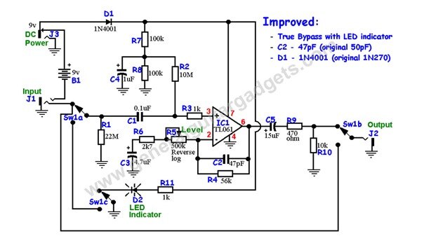
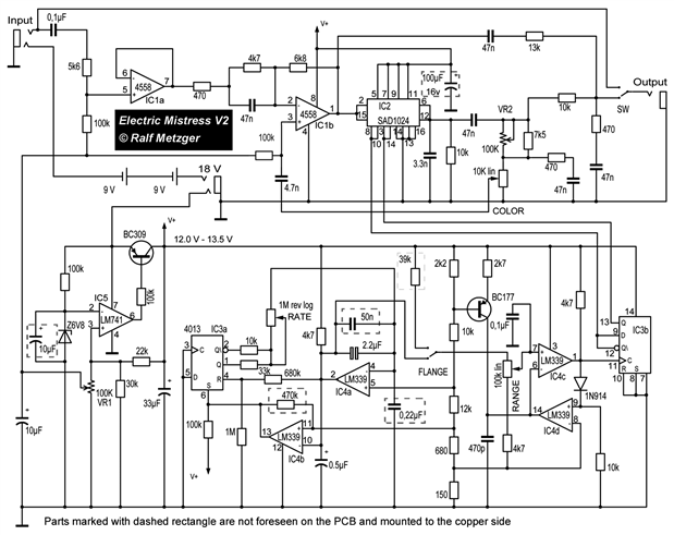
Ok... Here's my plan. I have 2 effects pedals... An electric mistress which runs on 18v (it actually has a voltage regulator inside it with reduces the voltage to around 13v but it does run on 2 9v batteries), the second pedal is a boost pedal which runs a single 9v battery which i currently run after the electric mistress to boost the output. The problem with the electric mistress is when you engage the effect the output volume drops by around 10 to 15%, so the boost pedal compensates for that drop.


What i want to do is build the boost circuit into the electric mistress enclosure.. so the guitar will go into the electric mistress travel through the mistress circuit to the output of the circuit then into the boost circuit, then to the output jack socket. Simple, but i have a dilema inso far as they each run on different voltages, so how can i regulate the 18v DC down to 9vdc for the boost part of the circuit? If they both ran on the same voltage it'd be easy.... but i'm a little lost with this.


I've been told to use a resistor but I've also been told that's not the right way to do it.... Any ideas?

  • Sign in to reply
  • Cancel

Top Replies

  • jw0752
    jw0752 over 7 years ago in reply to jc2048 +9
    Hi Jon, I have run a three simple tests and here are the results. I have Breadboarded an LM7809 on the left of the breadboard and a Recom R78C9.0-1.0 on the right side. Both have been provided with input…
  • genebren
    genebren over 7 years ago in reply to genebren +7
    Andy, I found the schematic that you had posted awhile ago (TL061 op-amp), and it looks like the circuit will operate at 18V. The only thing that you might need to check are the voltage ratings on you…
  • three-phase
    three-phase over 7 years ago +6
    I believe a simple 9V DC regulator will achieve what you need. You will be able to feed the 18V into this and it will produce the 9V output to run the boost pedal. L7809 9V/1.5A regulator The device above…
Parents
  • Andy Betts
    Andy Betts over 7 years ago

    Blimey..... I leave, turn my back for a bit and there's loads of responses. You guys are just great.... Many thanks for your input on this.


    For those that are asking here is the schematic of the boost:


    image


    This schematic is the one I built on a blog post. The 500k rev log pot will be replaced by a trimmer as it will be inside the pedal enclosure. Once the output has been set that's it.


    The Electric mistress circuit diagram is here:


    image


    Just to set one thing straight.... Although the Mistress runs technically on 2 9v batteries this one if set up to run off a 18v power supply as there's physically no room in the enclosure for the batteries. I have effectively removed the battery snap from inside and installed a DC power socket.

    • Cancel
    • Vote Up +2 Vote Down
    • Sign in to reply
    • Cancel
Reply
  • Andy Betts
    Andy Betts over 7 years ago

    Blimey..... I leave, turn my back for a bit and there's loads of responses. You guys are just great.... Many thanks for your input on this.


    For those that are asking here is the schematic of the boost:


    image


    This schematic is the one I built on a blog post. The 500k rev log pot will be replaced by a trimmer as it will be inside the pedal enclosure. Once the output has been set that's it.


    The Electric mistress circuit diagram is here:


    image


    Just to set one thing straight.... Although the Mistress runs technically on 2 9v batteries this one if set up to run off a 18v power supply as there's physically no room in the enclosure for the batteries. I have effectively removed the battery snap from inside and installed a DC power socket.

    • Cancel
    • Vote Up +2 Vote Down
    • Sign in to reply
    • Cancel
Children
  • michaelkellett
    michaelkellett over 7 years ago in reply to Andy Betts

    The booster circuit will run fine from 18V. Increase R11 to 2k if the LED is too bright.

    As drawn the LED will use about 16mA with an 18V supply, way more than the circuit itself.

    The booster should have a decoupling capacitor (0.1uF to 1uF ceramic) across the TL061 pins 7 and 4.

    The TL061 is not the optimum chip of its type here, it's the low current version, use a TL071 for lower noise, it'll use a bit more current but nothing like as much as that LED !


    MK

    • Cancel
    • Vote Up +2 Vote Down
    • Sign in to reply
    • Cancel
  • Andy Betts
    Andy Betts over 7 years ago in reply to michaelkellett

    Michael, as the boost will be built into the mistress enclosure i'll not be using the LED so the resistor is redundant

    • Cancel
    • Vote Up +1 Vote Down
    • Sign in to reply
    • Cancel
  • geralds
    geralds over 7 years ago in reply to Andy Betts

    Hm ,,, I found both circuits in the websites under Goooooo
    You use these circuits?


    Well, the Boost amp can be easily operated with this V++ 13.5V after the voltage regulation.
    But above all else, the 18V could probably be used as a phantom power for a subsequent or pre-connected circuit. Is that so?
    Then you probably also have to pay attention to the circuit direction of the pawls.

    Yes, the TL071 would be a good alternative. But very low noise would not be the domain here.


    But if you want to tinker, then you can exchange the other ICs for more modern parts that need less power.

    For example, the voltage regulator can also be made cheaper with a 3-leg regulator instead of the 741 and Zener / transistor.

    The same applies to the 4-fold comparator and the NE4558, which are already very old gentlemen.

    So a good weighting of anything can add value to such a pedal.


    TL084 (4 OPAMPs in one housing) for all audio buffers, and the regulator (if you not like to change it to a 3-leg device), and the regulator feedback voltage

    as the reference voltage for the delay SAD1024 can be made cheaper.

    http://www.pmerecords.com/Docs/Archer_SAD-1024_Tech_Data.pdf

    The comparator can be CMOS version, so the 4013 D-FF would be optimal sourced with that. -> Fan-in / fan-out, the comparator resistors can be higher as well, it saves current.

    All in all the layout would also be a bit smaller as well mounted with SMD. Last but not least using a low current LED can save current as well.


    …. last idea: do you like to program an µC? so you can rebuild a mistress in digitally kind.


    Best Regards

    Gerald

    ---

    Attachments:
    imageSAD1024_Reticon.pdf
    • Cancel
    • Vote Up +2 Vote Down
    • Sign in to reply
    • Cancel
element14 Community

element14 is the first online community specifically for engineers. Connect with your peers and get expert answers to your questions.

  • Members
  • Learn
  • Technologies
  • Challenges & Projects
  • Products
  • Store
  • About Us
  • Feedback & Support
  • FAQs
  • Terms of Use
  • Privacy Policy
  • Legal and Copyright Notices
  • Sitemap
  • Cookies

An Avnet Company © 2025 Premier Farnell Limited. All Rights Reserved.

Premier Farnell Ltd, registered in England and Wales (no 00876412), registered office: Farnell House, Forge Lane, Leeds LS12 2NE.

ICP 备案号 10220084.

Follow element14

  • X
  • Facebook
  • linkedin
  • YouTube