element14 Community
element14 Community
    Register Log In
  • Site
  • Search
  • Log In Register
  • About Us
  • Community Hub
    Community Hub
    • What's New on element14
    • Feedback and Support
    • Benefits of Membership
    • Personal Blogs
    • Members Area
    • Achievement Levels
  • Learn
    Learn
    • Ask an Expert
    • eBooks
    • element14 presents
    • Learning Center
    • Tech Spotlight
    • STEM Academy
    • Webinars, Training and Events
    • Learning Groups
  • Technologies
    Technologies
    • 3D Printing
    • FPGA
    • Industrial Automation
    • Internet of Things
    • Power & Energy
    • Sensors
    • Technology Groups
  • Challenges & Projects
    Challenges & Projects
    • Design Challenges
    • element14 presents Projects
    • Project14
    • Arduino Projects
    • Raspberry Pi Projects
    • Project Groups
  • Products
    Products
    • Arduino
    • Avnet Boards Community
    • Dev Tools
    • Manufacturers
    • Multicomp Pro
    • Product Groups
    • Raspberry Pi
    • RoadTests & Reviews
  • Store
    Store
    • Visit Your Store
    • Choose another store...
      • Europe
      •  Austria (German)
      •  Belgium (Dutch, French)
      •  Bulgaria (Bulgarian)
      •  Czech Republic (Czech)
      •  Denmark (Danish)
      •  Estonia (Estonian)
      •  Finland (Finnish)
      •  France (French)
      •  Germany (German)
      •  Hungary (Hungarian)
      •  Ireland
      •  Israel
      •  Italy (Italian)
      •  Latvia (Latvian)
      •  
      •  Lithuania (Lithuanian)
      •  Netherlands (Dutch)
      •  Norway (Norwegian)
      •  Poland (Polish)
      •  Portugal (Portuguese)
      •  Romania (Romanian)
      •  Russia (Russian)
      •  Slovakia (Slovak)
      •  Slovenia (Slovenian)
      •  Spain (Spanish)
      •  Sweden (Swedish)
      •  Switzerland(German, French)
      •  Turkey (Turkish)
      •  United Kingdom
      • Asia Pacific
      •  Australia
      •  China
      •  Hong Kong
      •  India
      •  Korea (Korean)
      •  Malaysia
      •  New Zealand
      •  Philippines
      •  Singapore
      •  Taiwan
      •  Thailand (Thai)
      • Americas
      •  Brazil (Portuguese)
      •  Canada
      •  Mexico (Spanish)
      •  United States
      Can't find the country/region you're looking for? Visit our export site or find a local distributor.
  • Translate
  • Profile
  • Settings
Industrial Automation
  • Technologies
  • More
Industrial Automation
Blog AVNET SmartEdge IIOT Gateway: try MODBUS with RS-485
  • Blog
  • Forum
  • Documents
  • Quiz
  • Events
  • Polls
  • Files
  • Members
  • Mentions
  • Sub-Groups
  • Tags
  • More
  • Cancel
  • New
Join Industrial Automation to participate - click to join for free!
  • Share
  • More
  • Cancel
Group Actions
  • Group RSS
  • More
  • Cancel
Engagement
  • Author Author: Jan Cumps
  • Date Created: 15 Aug 2022 7:28 PM Date Created
  • Views 1057 views
  • Likes 7 likes
  • Comments 0 comments
  • raspberry
  • smartedge
  • rs-485
  • modbus
  • linux
Related
Recommended

AVNET SmartEdge IIOT Gateway: try MODBUS with RS-485

Jan Cumps
Jan Cumps
15 Aug 2022

I'm learning the MODBUS protocol. I'll first try it on Linux devices. My first step is to learn the core data exchange mechanisms and transport layer options.
Transport layer options are TCP/IP and serial. I'm going to start with serial communication. This works with any UART (USB, RS-232, RS-485). I'm using RS-485.
image  image
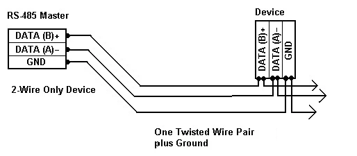
image source: left: me, right: edited from one of many sources of the same image
For the Linux exercise, I'm using two AVNET SmartEdge IIOT Gateways. They have an RS-XXX port that I configured as RS-485 on both, and connected using the schematic above. The SmartEdge user guide tells me that the character device for the RS-XXX is /dev/ttySC0.

To use LIBMODBUS, you need to have the libmodbus package installed on your Linux box. If you want to build the code on that Linux box, you also need to have the libmodbus-dev package. I'm cross-compiling from a windows PC, so my Linux device only needs libmodbus. On my windows machine, I copied the library from the Linux file system, and got the MODBUS header files from github.

To build the executables on Linux, here's the command line:
gcc -I /usr/include/modbus <module>.c -o <module> -L/usr/lib/modbus -lmodbus

As example, I used a gateway and sensor example from Julien Grossholtz. My development environment is Eclipse on Windows, with an ARM cross-compile GCC toolchain.

The sensor code is a demo. It reads two attributes from the processor and puts that in the MODBUS payload. The original example uses two temperature zone measurements. My AVNET device (a Pi derivative) only has one temperature zone, so I selected processor frequency as a second data point.

/Simple function that grab temperature and frequency on my Pi and copy it to the mapping
//structure from libmodbus ( this code is for test purpose ).
void update_telemetry(modbus_mapping_t *mb_mapping)
{
	FILE *f1,*f2;
	uint32_t temp,freq;
	size_t s;

	f1 = fopen("/sys/class/thermal/thermal_zone0/temp","r");
	fscanf(f1,"%"PRIu32,&temp);
	temp = temp/1000;
	mb_mapping->tab_registers[0] =(uint16_t) temp;

	f2 = fopen("/sys/devices/system/cpu/cpu0/cpufreq/scaling_cur_freq","r");
	fscanf(f2,"%"PRIu32,&freq);
	freq = freq/1000;
	mb_mapping->tab_registers[1] =(uint16_t) freq;

	fclose(f1);
	fclose(f2);
}

The only other changes I made was the character device filename and the speed. In both files.

#define UART_PATH "/dev/ttySC0"
// #define UART_PATH "/dev/ttyUSB1"
#define BAUD (9600)

// ...
	//Set uart configuration and store it into the modbus context structure
	ctx = modbus_new_rtu(UART_PATH, BAUD, 'N', 8, 1);

Here is a screenshot with both programs running (and being debugged), each on a different Gateway.

image
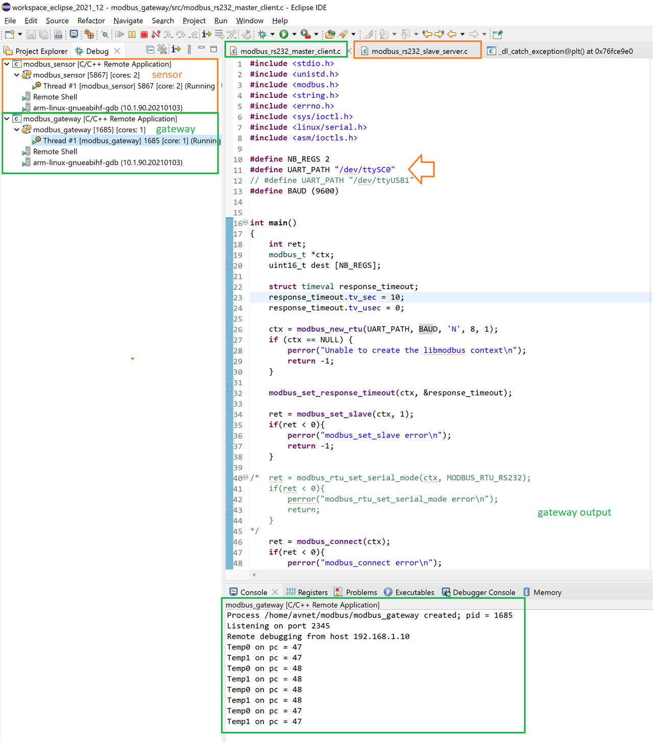
You may spot that the output shows 2 identical temperatures. That's because I hadn't incorporated the CPU frequency in the sensor code yet (I used zone0 temperature for the two MODBUS register values). Here is the data exchange after that modification.
image

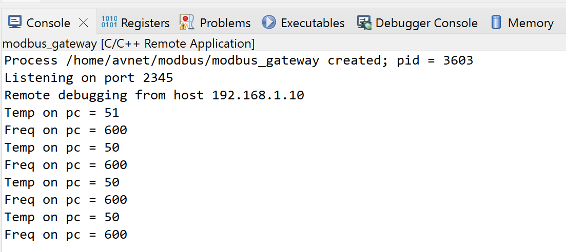
Some highlights on the example:

  • It uses RTU (binary) data protocol. MODBUS has a second one: ASCII.
  • The MODBUS address of the sensor device is 0
  • Two data points (registers) are exchanged.
  • Sign in to reply
element14 Community

element14 is the first online community specifically for engineers. Connect with your peers and get expert answers to your questions.

  • Members
  • Learn
  • Technologies
  • Challenges & Projects
  • Products
  • Store
  • About Us
  • Feedback & Support
  • FAQs
  • Terms of Use
  • Privacy Policy
  • Legal and Copyright Notices
  • Sitemap
  • Cookies

An Avnet Company © 2025 Premier Farnell Limited. All Rights Reserved.

Premier Farnell Ltd, registered in England and Wales (no 00876412), registered office: Farnell House, Forge Lane, Leeds LS12 2NE.

ICP 备案号 10220084.

Follow element14

  • X
  • Facebook
  • linkedin
  • YouTube