


Table of Contents
Introduction
I had a requirement to measure temperature, and I wanted to use off-the-shelf hardware for now. Looking around for what was available, it seemed that an RS-485 connection, transporting content known as Modbus RTU frames, might work for me.
This short blog post explains how to use Modbus RTU with the thermocouple temperature acquisition device, in case anyone else has a similar need.
But first, a brief explanation of the Modbus RTU protocol.
What Is Modbus RTU?
Modbus RTU is a protocol with a simple request-response format, where the client (master) sends the requests. You can use Modbus RTU to set values, or to read them. Only a few different data types are supported, and they have unusual names for historical reasons.
| Data Type | Size | Description |
| Coil | 1-bit (On/Off) | Actuator state (e.g. relay coil) |
| Discrete Input | 1-bit | A binary input (e.g. switch) |
| Input Register | 16-bit | Usually a varying value, perhaps from a sensor |
| Holding Register | 16-bit | Similar to above register, but typically for configuration values that seldom change (perhaps in non-volatile memory) |
A typical modbus frame contains:
<address><function_code><bytes_stream><16_bit_checksum>
The bytes stream depends on the function code. There are different function codes to read a range of any of the four data types listed above, and to write one or multiple values of data, plus there are various other miscellaneous functions.
The response overall looks very similar to the request (which makes it sometimes impossible to visually distinguish with complete certainty a request from a response!; that's a clue to how ancient this protocol is), and the bytes stream will vary depending on the function code. Usually, the stream will begin with a length byte, and then perhaps a list of 16-bit values might be returned, or binary values packed into bytes.
The diagram below shows the formats for an example request, and a valid response, and an error response (which has the most significant bit set within the function code byte).

Here are the hex bytes of an example request, for querying the values of 16-bit input registers #0 and #1:
01 04 00 00 00 02 71 CB
Breaking that down, the first byte indicates the address of the device that is to respond. The second byte is function code 0x04, which is “Read Input Registers”. The next two bytes are the 16-bit address of the first desired register. The next two byes specify how many registers are to be read. Finally the last two bytes are a checksum for all the preceding bytes.
A successful response to that will contain the same address and function code as the request, but then there will be a 1-byte length field, and then the list of 16-bit register contents, followed by the checksum. Example:
01 04 04 AA BB CC DD 3F 20
In that example response, the first register value is 0xAABB, and the second register value is 0xCCDD.
Regarding register numbering, another interesting historical-based point to note, is that sometimes the registers are listed as very large numbers such as 30001, 30002 and so on; those are for display purposes (to distinguish different data types, the 10000 series would be Discrete Inputs [binary values] for example), and in reality, at the actual protocol level, it’s likely you need to use addresses from zero upward, not from those large numbers.
For more detail about the Modbus RTU protocol format, please see https://github.com/shabaz123/modbus_tools/blob/main/modbus_rtu_format.md
For the checksum algorithm (in microcontroller-friendly C code) see https://github.com/shabaz123/modbus_tools/tree/main/modbus_rtu_crc16
What is Modbus TCP?
Only partially relevant to this blog post, but there’s a fair bit of similarity. As the name suggests, Modbus TCP uses TCP/IP instead of RS-485. The PDU in the earlier diagram remains the same, but there’s no need for a CRC (TCP/IP is already reliable), and the Additional Address byte is replaced by seven bytes called a Modbus Application Protocol (MBAP) header.
In summary, the Modbus TCP protocol is as straightforward to understand as is Modbus RTU, so if required, a microcontroller with a network connection would be feasible to interface with a Modbus TCP device.
RS-485 Refresher
It’s a three-wire system (two carrying serial data in differential (balanced) pair, and a ground or 0V reference wire) and multiple devices can connect to it. The two balanced wires are called A and B, or Normal and Inverting respectively. When one of those two wires is high with respect to the 0V connection, then the other wire will be low, and vice-versa.
Transmit and receive can occur over the same set of wires, therefore it’s best if all devices are usually set as inputs, and only when a device needs to send data, should that device become an output.
Most microcontrollers only offer a UART that has separate connections (often called RXD and TXD) for normal single-ended receive and transmit signals. Therefore, a kind of switchable buffer/level converter chip, called an RS-485 transceiver, is needed, to interface between the microcontroller connections and the balanced A and B wires, and the transceiver must be able to divert the stream from RXD (microcontroller input) to TXD (microcontroller output) depending on if the microcontroller receiving or needs to transmit.
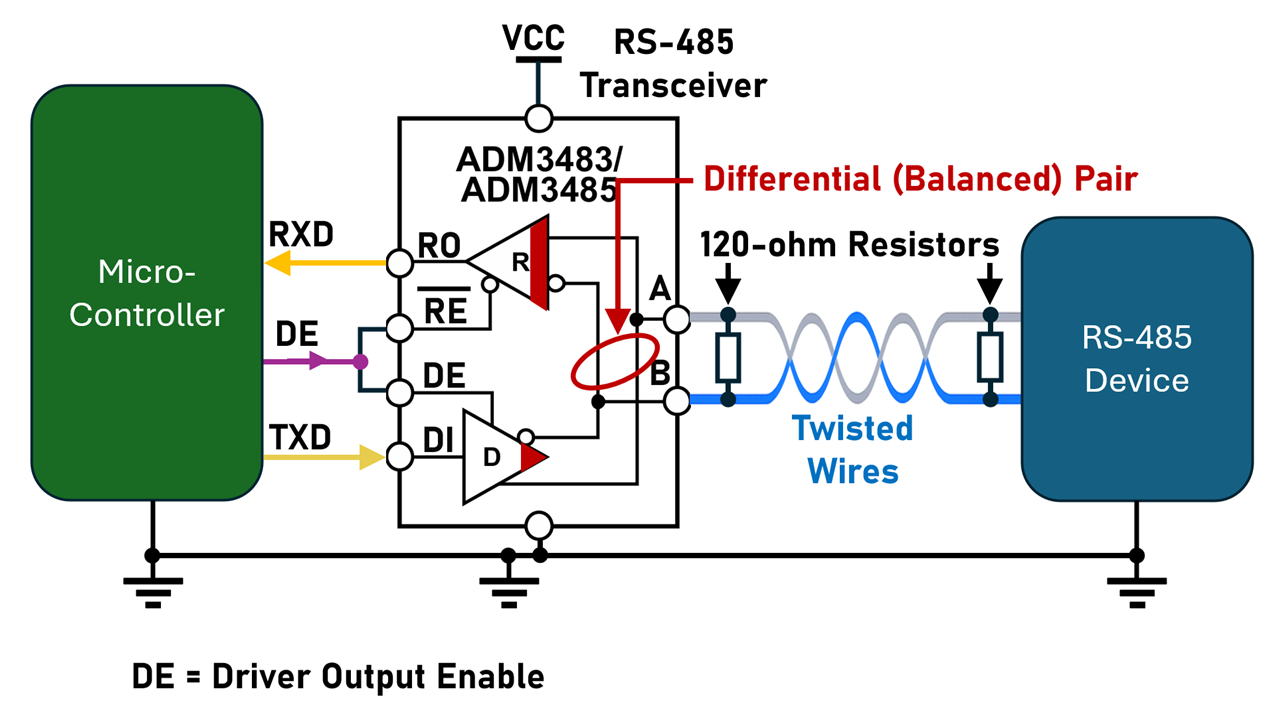
Some RS-485 transceivers can automatically do this, but another technique is to allocate a third pin on the microcontroller, to act as the signal to switch the transceiver direction. Usually, that third wire from the microcontroller needs to go high whenever the microcontroller code needs to transmit, to switch the RS-485 transceiver direction accordingly. That third wire is labelled DE (Driver Output Enable) in the example diagram above.
Multi-Channel Thermocouple Adapter
I purchased a low-cost thermocouple adapter, and it’s not bad. The instructions were only in Chinese, so I had to do some auto-translation.
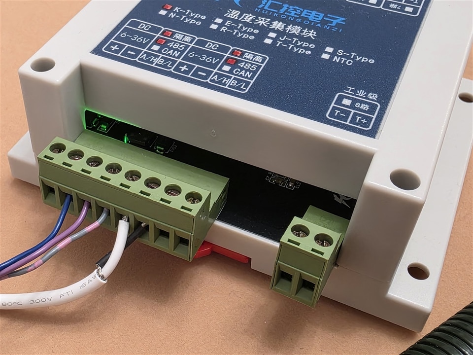
The internals look pretty good, unfortunately I didn't take any better photos.
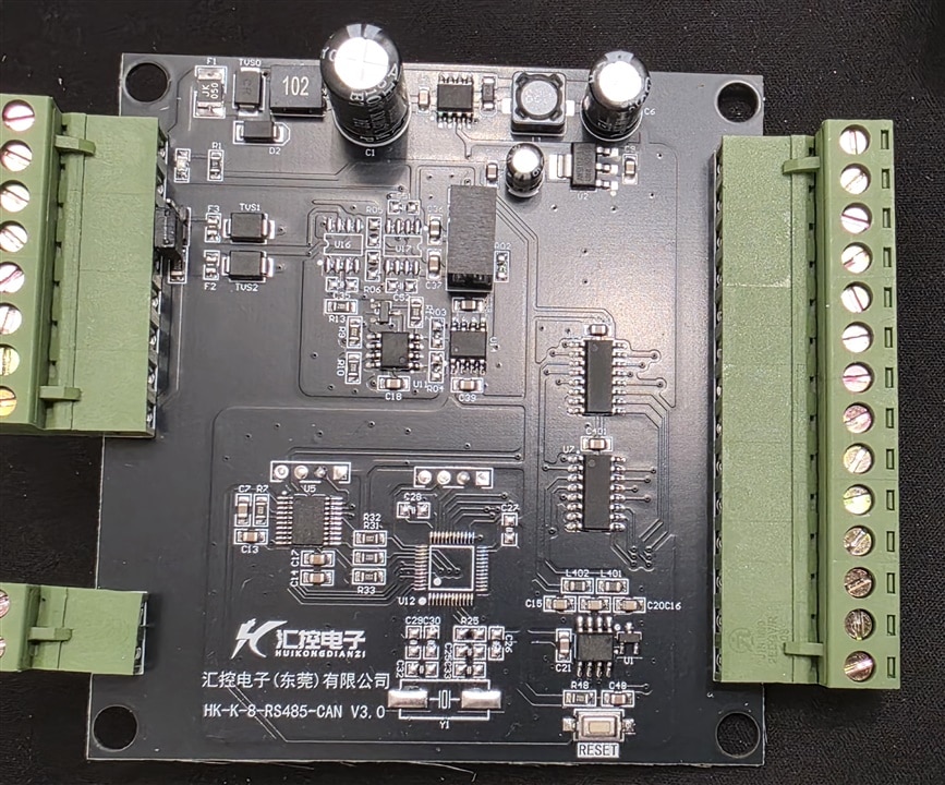
The product code is HK-K-8-RS485-CAN V3.0 and is called a K-type Thermocouple Temperature Acquisition Series by Huikong Electronics (Dongguan) Co., Ltd.
Product Description
• 1-16 channels (depending on model)
• Up to 10 Hz update per channel
• Isolated RS-485
• Modbus RTU
• Open Circuit detection
• CJ Compensation
• Measuring range: -200 to +1350 deg C
• Resolution: 0.25 deg C
• Accuracy: +- 3 deg C
• LEDs: Power, Comms
• Reliability: Hardware and Software Watchdog
• STM32 ARM Microcontroller
• 14-bit ADC
• Isolation: 3kV
• C45 (35mm) DIN rail mount
Product Specifications
|
Item |
Description |
|
Supply Voltage |
6-36V DV |
|
Interface |
Isolated RS-485 |
|
Power Consumption |
< 200mW |
|
Measurement Range |
-200 to + 1350 degC (K-type sensor) |
|
Collection Channels |
1-8 |
|
ADC Resolution |
14-bit |
|
Temperature Resolution |
0.25 deg C |
|
Accuracy |
+- 3 deg C |
|
Sample Rate |
100 kHz |
|
Data Update Rate |
Up to 10 Hz Per Channel |
|
Sensor Type |
K-Type |
|
Cold Junction Compensation |
Present |
|
Fault Detection |
Sensor Disconnected, Open Circuit |
|
Communication Protocol |
Modbus RTU |
|
Supported Function Codes |
0x03 = Read Holding Register 0x04 = Read Input Register 0x06 = Write Single Holding Register 0x10 = Write Multiple Holding Registers |
|
Data analysis method |
1 decimal place |
|
Slave Address |
1-255 (Configurable, Non-Volatile storage) |
|
Baud Rate |
4800, 9600, 14400, 19200, 38400 [default], 56000, 57600, 115200 (Configurable, Non-Volatile storage) |
|
Reset capability |
Hardware button, software reset |
Default Communication Settings
• Address: 0x01
• RS-485 settings: Baud: 38400, 8-bit data, no parity, 1 stop bit
Input Registers (Temperature Values)
Input registers are used to access the data acquisition values.
• Read-only
• 16-bit (two bytes)
Format:
Note: The format is NOT 2’s Complement.
Bit 15 (most significant bit) represents the sign (0 = positive, 1 = negative)
Bits 14:0 represent the temperature in tenths of a degree C.
Examples:
+50 degrees C is represented as 500 decimal, which is binary 0000 0001 1111 0100.
-50 degrees C is also represented as 500 decimal, but with MSB set to 1, i.e. 1000 0001 111 0100
Register Numbering:
The register numbering in the Modbus RTU protocol begin at 0, so for the 8-channel model, the registers are 0x0000 to 0x0007. For display purposes, that would be 30001 to 30008.
Holding Registers
Holding registers are used to store configuration values.
• Read/Write capability
• 16-bit unsigned integers (two bytes)
Register Numbering
|
Register Address |
Display Address |
Reset Value |
Description |
|
0x0031 |
40050 |
0 |
Data upload time interval in hundredths of a second. Example: Register value 200 means 2 / 100 = 2 seconds. Register value 0 means no active data upload. |
|
0x0032 |
40051 |
1 |
RS-484 Address (1-255). Changes take effect after power cycle |
|
0x0033 |
40052 |
1 |
Baud Rate. Mapping: 1=9600, 2=14400, 3=19200, 4=38400(default), 5=56000, 6=57600, 7=115200 |
|
0x003d |
40062 |
0 |
RS-485 Parity. Mapping: 0=No Parity (default), 1 = Odd, 2 = Even. Changes take effect after power cycle |
Testbed
The busy photo here shows how everything was connected up. My setup used a USB-to-I2C adapter, followed by a I2C-to-UART adapter, and then the RS-485 transceiver, so it’s more involved than what would normally be done. I had various reasons not important for this blog. It would be far easier to use a USB-Serial adapter followed by an RS-485 transceiver, or, simpler still, buy a USB-to-RS485 adapter.

Results
I won’t go into the software, since it’s so specific to my needs, however, you can see the hex bytes that formed the Modbus RTU request, and the response, in the screenshot below! This was based on the format description already described in this blog post. The temperature measurement looks realistic, and goes up when the thermocouple is warmed up. I do have a thermocouple simulator, I could use that to measure the accuracy of the device at some point, but I’ve no reason to doubt the specification so far.

Troubleshooting
If one gets in trouble, then generally WireShark is a good application to try! It will decode Modbus TCP, however Modbus RTU requires a way of getting WireShark to accept the serial data. There are various tools for that, some purchaseable, but, it strikes me that an easy approach would be to use a cheap microcontroller (such as a Pi Pico) to sniff the RS-485, and send it to the PC, and let the PC convert to Modbus TCP, back-and-forth over a local (127.0.0.1 IP address) connection. Then, WireShark can simply decode as Modbus TCP. I have got some distance into implementing this, but it's a work-in-progress.
Summary
This blog post walked briefly through an RS-485 and Modbus RTU protocol overview. Modbus RTU is easy to begin experimenting with, using a PC or microcontroller, and a serial connection and an RS-485 transceiver. It was possible to purchase an off-the-shelf Modbus RTU compatible temperature acquisition unit, and query 16-bit “Input Registers” which contained the measured temperature results.
Thanks for reading!