


Introduction
After playing with Infineon's motor shield, I remembered I have taken notes and photographs of motors at various points in time in the past. It seemed like a good time to collect them together and review different types of motors. Motors are expensive, so any internal photos people have of them would be gratefully appreciated.
There are many types of motors, and some popular varieties are discussed here. AC motors are not covered. One way of classifying the various types is by observing which elements of the motor compose the stator (the fixed, non-moving part), and which elements form the rotor.
| Motor Type | Stator (non-moving part) | Rotor (moving part) |
|---|---|---|
| Permanent magnet DC (PM DC) | Magnets | Windings |
| Brushless DC (BLDC) | Windings | Magnets |
| Servo | Magnets | Windings |
| Stepper | Windings | Magnets |
| Moving Coil | Magnets | Windings |
Permanent magnet DC motor
One of the most commonly encountered is the permanent magnet DC motor. The classic motor in this genre usually has two magnets, three windings on a laminated structure and brushes and ‘commutator’ segments (also known as bars) which the brushes rub against. It is the latter characteristic which gives it the name ‘brushed motor’. If the shaft is rotated by hand, it may be noticed that the motor appears to want to settle in certain positions; when the motor runs, this is known as ‘cogging’ and is an undesirable characteristic. More advanced motors reduce this effect by having diagonally shaped slots for the windings in the laminated structure, or more than three windings.
Often motors for industrial applications may have additional windings and commutator segments to have more consistent torque as the motor rotates.
The photo here shows the brushes of a low cost motor:

Here you can see the rotor and three commutator segments:

The rotor removed from the motor; the windings and the connections to the commutator segments are now more visible:

Brushless DC (BLDC) motor
As their name implies, these motors do away with the need for the brushed commutator. Instead, they rely on electronic commutation. The windings are fixed, and the magnets revolve. In an almost inside-out configuration, the windings can be in the center of the motor facing outward, and the magnet shell rotates around the motor. In order to provide correct commutation, the circuit needs to know which winding to energise, and this can be determined through the use of hall sensors. ‘Sensor-less’ operation is possible in certain scenarios, by relying on monitoring the back EMF from an unenergised winding. The control system can be dedicated hardware or a microcontroller. BLDC motors are implemented as part of hard disks; they operate sensor-less and so when they are started up, the control system relies on the initial back EMF after a pair of windings have been energised to determine which windings to energise next. When they are running, the back EMF provides the feedback to determine exactly when the windings should be energized for smooth operation. The photograph here shows the stator from a laptop hard disk.

Floppy disk drives can contain a flattened implementation of a BLDC (the rotor was removed, it can be seen on the left of the photo):

Servo motor
Servo motors can be considered as conventional motors but with feedback attached to the shaft (perhaps indirectly through gearing). In radio control toys, a servo is a complete unit containing a DC motor, gearing a potentiometer varies according to servo rotated position and a small circuit which accepts a PWM input to control the system. Another servo motor that is encountered is for industrial applications such as CNC. Here the servo motor (or, alternatively, a stepper motor – see later) is used as part of automated machining processes. Higher accuracy is demanded and encoder methods are used to determine the position of the shaft and to provide this feedback to the servo circuit.
Stepper motor
The stepper motor provides accurate positioning control through the use of multiple windings which can be energised in a sequential fashion by an external circuit. By energising multiple windings, half-step and micro-stepping allows for even higher resolution positioning. Furthermore the need for optical feedback is reduced or eliminated, for both position and speed determination. Stepper motors are sometimes encountered in CNC applications. The stepped response from the motor can result in mechanical resonating effects at certain speeds, however, and this would be disastrous for industrial applications; the problem is mitigated through damping which can be achieved in several ways; through processing of the current passed through the windings, or through mechanical means. At a high level, a stepper motor may sound similar to a brushless DC motor; but the uses are different; stepper motors are often designed for positional accuracy at the cost of speed, whereas a BLDC motor can operate at very high speeds.
Stepper motors can have a few topologies; the photo here shows the rotor removed from the inside of a stepper motor known as a can stack stepper motor:

This is what the coils look like:

There are only two coils, and each coil when energised will have a north and south pole (for example, the black plastic end that is visible could be the north pole. When assembled, there is a mesh of fingers; these extend the pole into the ring, so that there are alternating north and south poles along the inner circumference of the ring. The rotor also has multiple alternating poles all around the outside.
Moving coil motor
This is a variation of the permanent magnet DC motor, also known as a ‘voice coil’ motor due to its similarity to the voice coil in a loudspeaker .A certain form of it is found in hard disk drives, to control the position of the hard drive head. In this form, the motor sweeps for less than a complete revolution. Naturally a motor of this type needs to exhibit not just high speed, but extremely low inertia for a rapid response time. It is achieved by eliminating the iron core from the motor winding, and relying on a thin, lightweight material. The motor has been ‘flattened’ so that it consists of a sandwich of flat winding between magnets. Not shown in the photograph is the covering which contains the top magnet in the sandwich.
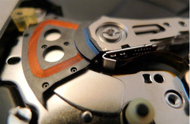
The unusually shaped coil plays an important role; each magnet is polarized such that the magnetic force created from the current in each of the two radial portions of the coil adds together.
Another form of moving coil motor more closely resembles a conventional permanent magnet DC motor, but offers some high performance features. Several manufacturers offer moving coil motors where the coil is wound in a hollow, tube form which revolves around a central magnet. The rotor shaft may run down the center of the magnet. The shell of the motor forms part of the path for magnetic flux. The high performance features include high speed because there is no heavy laminated iron core.
Summary
This post was really just to document some different motor implementations, so that they can be easily recognized and their properties understood.
As mentioned earlier motors are too expensive to want to take apart, so the bare minimum motors were harmed in the making of this blog post.
Top Comments