I was surfing the net looking for inspiration to build something new to me when I stumbled across Building a Voltage-Controlled Oscillator (VCO) by shabaz .
His blog post inspired me quite a lot, but also showed me the amount of work and test needed to build something like this and since I have absolutely no experience in this field, I took a step back and decided to build a simpler oscillator.
Going back to university lessons, I brought back the one where we talked about oscillators and used it as base to design a Colpitts oscillator. Added a couple resistors for DC biasing my bjt and started designing it. Since it's just for learning, I don't have any stringent requirement. I'm shooting for an oscillation frequency around 10MHz and an output waveform that could resemble a sine.
After a couple iterations on paper I was happy enough with the result. After a quick verification with LTspice using a 2N2222 I was ready and impatient to build my circuit.
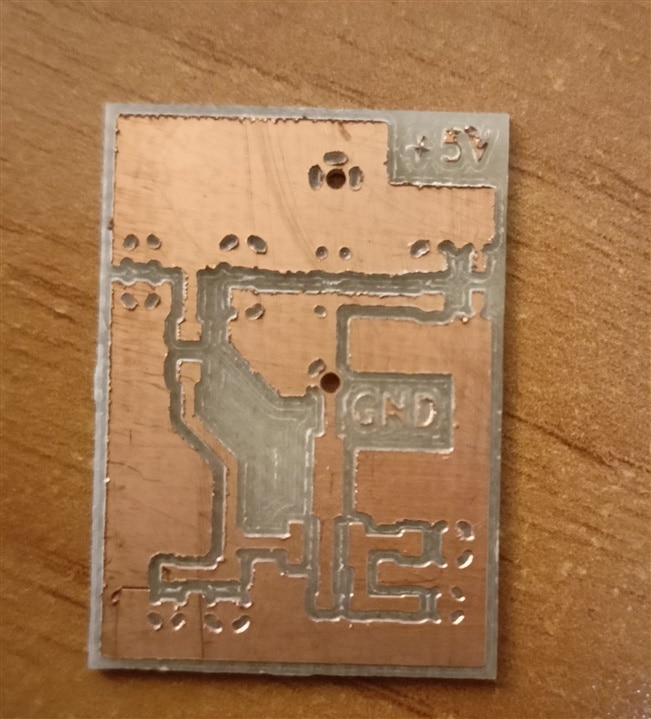
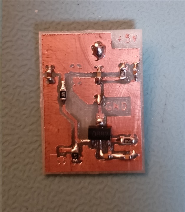
Powered up the circuit and... nothing happened. The output sadly wasn't showing any oscillation.
Back to the paper (and the simulator), I realized I made some rookie mistakes:
- First of all, 2N2222 used for the first simulation is nowhere similar to the D882 I'm using in the actual circuit. Using a similar bjt the simulation is correct and does not oscillate
- Feedback capacitors value is too small: I miscalculated loading effect on feedback network thus obtaining the wrong feedback ratio
- I did not include in my analysis the attenuation due to resistor network to bias my bjt instead of an ideal current/voltage source
After these corrections, I obtained this scheme:
This circuit no longer has the resonant frequency I initially hoped, instead it should resonate around 4MHz, which for me is "high enough". C3 in the scheme could be easily removed, but it was there from the previous revision and I did not remove it.
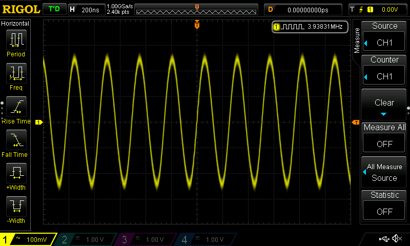
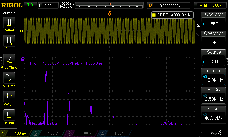
It works! Looking at the waveform in the time domain I was quite happy with the result: 500mVpp with an oscillation frequency just under 4MHz and no major distrortion.
FFT unfortunately tells me another story, with a calculated THD just over 4%. I guess it's fine, but I was hoping for a slightly better result.
Just for fun I decided to try measure the oscillation frequency using a DIY near field probe I made a couple years ago.
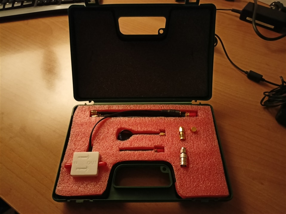
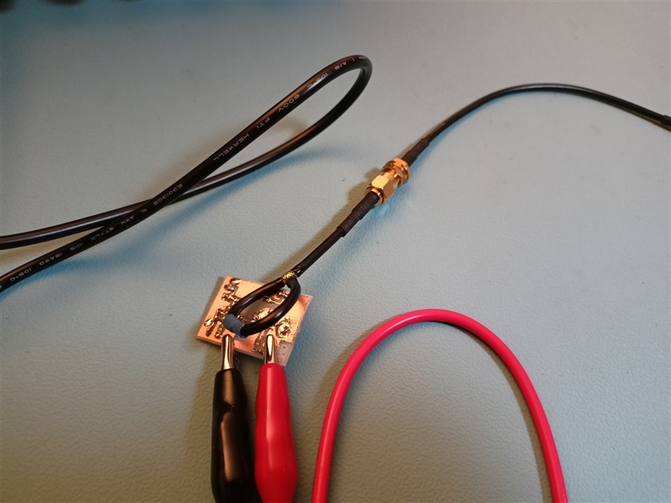
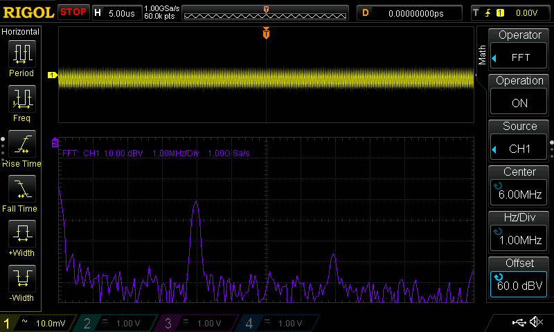
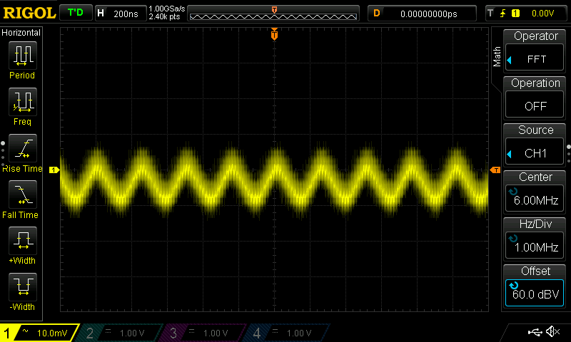
With the H field probe I was fortunate enough to be able to pick up a very faint signal, just enough to display first and second harmonic with the FFT.
Overall it was great fun and I've learned (once again! :) ) that it's better to not rush things (like I've done in the first revision of this circuit) just because I was impatient to see if the circuit works.
