element14 Community
element14 Community
    Register Log In
  • Site
  • Search
  • Log In Register
  • Community Hub
    Community Hub
    • What's New on element14
    • Feedback and Support
    • Benefits of Membership
    • Personal Blogs
    • Members Area
    • Achievement Levels
  • Learn
    Learn
    • Ask an Expert
    • eBooks
    • element14 presents
    • Learning Center
    • Tech Spotlight
    • STEM Academy
    • Webinars, Training and Events
    • Learning Groups
  • Technologies
    Technologies
    • 3D Printing
    • FPGA
    • Industrial Automation
    • Internet of Things
    • Power & Energy
    • Sensors
    • Technology Groups
  • Challenges & Projects
    Challenges & Projects
    • Design Challenges
    • element14 presents Projects
    • Project14
    • Arduino Projects
    • Raspberry Pi Projects
    • Project Groups
  • Products
    Products
    • Arduino
    • Avnet & Tria Boards Community
    • Dev Tools
    • Manufacturers
    • Multicomp Pro
    • Product Groups
    • Raspberry Pi
    • RoadTests & Reviews
  • About Us
  • Store
    Store
    • Visit Your Store
    • Choose another store...
      • Europe
      •  Austria (German)
      •  Belgium (Dutch, French)
      •  Bulgaria (Bulgarian)
      •  Czech Republic (Czech)
      •  Denmark (Danish)
      •  Estonia (Estonian)
      •  Finland (Finnish)
      •  France (French)
      •  Germany (German)
      •  Hungary (Hungarian)
      •  Ireland
      •  Israel
      •  Italy (Italian)
      •  Latvia (Latvian)
      •  
      •  Lithuania (Lithuanian)
      •  Netherlands (Dutch)
      •  Norway (Norwegian)
      •  Poland (Polish)
      •  Portugal (Portuguese)
      •  Romania (Romanian)
      •  Russia (Russian)
      •  Slovakia (Slovak)
      •  Slovenia (Slovenian)
      •  Spain (Spanish)
      •  Sweden (Swedish)
      •  Switzerland(German, French)
      •  Turkey (Turkish)
      •  United Kingdom
      • Asia Pacific
      •  Australia
      •  China
      •  Hong Kong
      •  India
      •  Korea (Korean)
      •  Malaysia
      •  New Zealand
      •  Philippines
      •  Singapore
      •  Taiwan
      •  Thailand (Thai)
      • Americas
      •  Brazil (Portuguese)
      •  Canada
      •  Mexico (Spanish)
      •  United States
      Can't find the country/region you're looking for? Visit our export site or find a local distributor.
  • Translate
  • Profile
  • Settings
Open Source Hardware
  • Technologies
  • More
Open Source Hardware
Forum Archaeology Resistivity Meter
  • Blog
  • Forum
  • Documents
  • Events
  • Polls
  • Members
  • Mentions
  • Sub-Groups
  • Tags
  • More
  • Cancel
  • New
Join Open Source Hardware to participate - click to join for free!
Actions
  • Share
  • More
  • Cancel
Forum Thread Details
  • Replies 332 replies
  • Subscribers 321 subscribers
  • Views 44626 views
  • Users 0 members are here
  • armp
  • archaeology resistivity meter
Related

Archaeology Resistivity Meter

kltm
kltm over 5 years ago

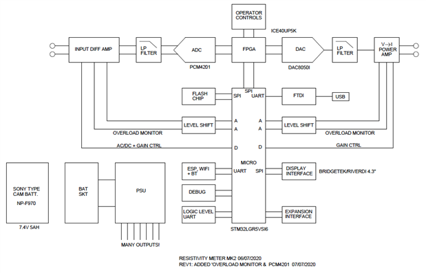
Hi I'm looking for ideas on an update to a resistivity meter for archaeology. The only published designs for diy were in 2 magazines. One was published in 1997 and the other in 2003. I have copies of both articles available. The reason behind this is the current high cost of available equipment, usually well beyond the reach of most archaeological groups. I've attached a basic block diagram. In the first magazine article the meter is very basic. It relied on the operators to write down the reading given as the survey was taken. Given that a normal survey grid is 20m x 20m and 1 reading is taken on every sq mtr there would be 400 readings to write down and then input into a program used to interpret the results. The later article is really an update to the first where a PIC has been added to record the readings. This again is prone to error, because eadings are taken manually by pressing a button.

I'm sure given the advances in electronics there must be better ways. 


image

  • Sign in to reply
  • Cancel

Top Replies

  • kltm
    kltm over 5 years ago in reply to michaelkellett +8
    Hi Michael This all sounds very interesting and encouraging. I see you have found the original article, the update is also on slideshare somewhere. I haven’t really thought much about cost, but as you…
  • michaelkellett
    michaelkellett over 5 years ago in reply to shabaz +7
    I can't live with that - I have to have symmetry The problem is that the Howland current pump doesn't constrain the voltage on the load at all when perfectly balanced - and my LTSpice model is unrealistically…
  • michaelkellett
    michaelkellett over 5 years ago in reply to michaelkellett +7
    AS promised - now for the phase sensitive detector. I couldn't easily model this in LTSpice, which is no great surprise because it needs multiplication and square roots. I used Simulink in MATLAB - which…
Parents
  • kltm
    kltm over 5 years ago

    image

    • Cancel
    • Vote Up +1 Vote Down
    • Sign in to reply
    • Cancel
Reply
  • kltm
    kltm over 5 years ago

    image

    • Cancel
    • Vote Up +1 Vote Down
    • Sign in to reply
    • Cancel
Children
  • michaelkellett
    michaelkellett over 5 years ago in reply to kltm

    Looks good.

    Do you think we need a spec next ?

    Might be worth hanging on a couple of days to get comments on the block diagram and thoughts so far.


    Things to think about on spec:


    Operating temperature range

    Endurance on one fully charged battery

    Max output current and voltage (if 20mA RMS and nearly 60V pk-pk won't do it's going to get a lot more expensive image)

    Input common mode range (max +/- 14.5V including signal) ref instrument internal ground.

    Max signal combined signal and common mode +/- 29V differential

    Input impedance - could be 100M if wanted but I think this is a bad idea - should be lower , maybe 1M - problem is that you want the option

    of input caps for AC coupling. If you have 100M input Z then you get -3dB at 10Hz with a 160pF input cap, but its impedance at

    150Hz is 6.6M which will make things noisy. I'd like the capacitor impedance to be no more than 50k at 150Hz = 22nF, with 100M input that gives

    a time constant of 2.2s so it may take ages to settle, I'm tempted to go for 10M or even lower input resistance to reduce that effect. (NB, the settling time

    of the AC coupling RC is nothing to do with the normal settling time of measuring - its to do with how long it takes the system to settle after a large DC

    bias is applied to the input.) Ideas / comments etc welcome. (AC coupling will be switchable.)


    Input protection - static discharge (8kV ?, 16kV ? - full lightning ? (please not !) - any ideas from the field.


    Operator controls - buttons - membrane key pads are expensive - nice push buttons are also expensive -  any ideas.

    Would a touch screen be any good in the field ?


    Well there's a good collection of random thoughts and comments.


    MK

    • Cancel
    • Vote Up +2 Vote Down
    • Sign in to reply
    • Cancel
  • davemartin
    davemartin over 5 years ago in reply to michaelkellett

    Ken,

    I'm just catching up, sorry to hear of your loss.


    Michael, will post some feedback on various points in a moment


    Dave

    • Cancel
    • Vote Up +2 Vote Down
    • Sign in to reply
    • Cancel
  • shabaz
    shabaz over 5 years ago in reply to kltm

    Hi Michael,


    I had these initial thoughts, but I've not had time to think things through (I have some time late Wednesday to do that):

    There was mention of more sense probes, but maybe the expansion interface is sufficient for that, since one could drive (say) a latching relay via that. Or maybe space for on-board relay?

    A minor point was, for the USB UART, for MCP2221 I already have Android code. But FTDI is totally fine too, i.e. if you've already got the schematic entered for that portion then it's quicker for me to just hunt for demo code for FTDI, if you let me know the chip number. Below is the the schematic I've used previously for the MCP2221 (it needs an external 3.3V regulator which probably the FTDI device doesn't, and has 4kV protection which likely isn't enough, I didn't place any additional ESD protection on this schematic).


    One other thought was for a test facility, if there was were four jumpers or four DIP switches on the board which would connect a potential divider across the source (two switches for that) and two switches to connect the sense wires to the divider. Maybe jumpers are easier. But probably there will be test points on the board for easy soldering of a mini test harness during software development anyway.


    image

    • Cancel
    • Vote Up +3 Vote Down
    • Sign in to reply
    • Cancel
  • michaelkellett
    michaelkellett over 5 years ago in reply to shabaz

    Hello Sabaz,

    I'd prefer the FTDI chip (FT230X) since I've used it before and had no problems - no regulator needed.

    It doesn't have good ESD protection either.


    I'll look at the Microchip part.


    I usually design boards with lots of test points , compatble with those little wire loop 'pins', or wires, since it's a pad with a 1mm hole.

    The full processor debug will be available and at least two FPGA pins.


    I'm leaving mpx till a later design and additional pcb. If the expansion interface carries some signals and power it can do almost  anything.


    MK

    • Cancel
    • Vote Up +3 Vote Down
    • Sign in to reply
    • Cancel
  • michaelkellett
    michaelkellett over 5 years ago in reply to michaelkellett

    I've looked at the Microchip part, very little to choose between it and FTDI, Microchip possibly better documented.

    I like both companies - so I'll go either way !


    BATTERY


    I have results form first battery test.

    These are nominal 7.4V 8.8Ah batteries from Amazon at £40 for two including a USB powered charger.

    Not an ideal way to power a dual charger for these batteries - it would be quite safe to charge them at 2A max each

    taking about 5hours, charging at less than 0.5A each is going to be slow.


    image


    image

    My electronic load can do a simple (constant current load) battery rundown test so I set it for 0.5A load and

    5.9V end point. The battery voltage has bounced back a little once the load was removed, which is not unusual.


    I've recorded 7.527 Ah, which isn't that bad for a dead cheap battery rated at 8.8Ah. Its fine for this application.

    It would be better to test at constant power, but the Rigol can't do that.

    I might have squeezed a bit more by ending at 5V (2.5V per cell) but experience tells me that there won't be much

    energy left between 2.95 and 2.5 volts per cell and it's not good for long life to repeatedly discharge to that level.


    I've got the battery on charge and I'll run it again, then I'll try the other one.


    I estimate that I got 54.2 Wh out of it - I'm looking for  a minimum of 30Wh for this application, so unless it dies

    very quickly it looks OK.


    MK

    • Cancel
    • Vote Up +3 Vote Down
    • Sign in to reply
    • Cancel
  • davemartin
    davemartin over 5 years ago in reply to davemartin

    Thoughts on power sources.


    Sony consumer-camera-style batteries are a great source, I've used them for probably nigh-on twenty years for portable kit where they're suitable. My introduction came via a broadcast TV production client for whom I used to design and manufacture equipment used for various motor- and power-sport broadcast, both telemetry/data-logging and video capture. In days of yore, pre solid-state recorders, the client used to use the Sony GVD miniature DV decks in resiliently-mounted housings, and for commonality, I designed my kit to use the same NPF batteries.


    Just a couple of issues to be aware of:


    Electrical: A few packs had/have inbuilt over-discharge protection, but many (especially non-Sony clones) don't, so the power input will need to sense and then shut-down before over-discharging the pack, as Michael just mentioned (an acquaintance last year came to me with a cheap LED lighting panel powered by NPFs, and he was bemoaning how the batteries were no longer taking/holding much charge despite only having a dozen or so cycles on them...). There needs to be ample warning, you don’t want to have to stop and do a battery change mid-grid as stopping mid-grid for even a few minutes can introduce a discontinuity (the equipment may resume measuring accurately, but the ground conditions may have changed).


    Mechanical: Most of those packs don't inherently have complete physical attachment. When the slide onto a holder, the terminals at one end connect with those in the holder and the battery is constrained by a cover or hatch; on the NPF style there are also a couple of slotted-hooks like those on, say, some PC case covers to help keep the battery aligned. Those are usually sufficient to hold the battery in the plane of the contacts and a modest spring pressure usually keeps the contacts connected. However, if the battery slides back out away from the contacts, the connection is broken and the hooks can disengage. Sony recorders with exposed batteries had a mechanical latch which sprang-up once the battery was in and would stop it sliding backwards; but many of the third-party plates don't have that feature. Those plates are great for charging and for low-dynamic power uses, but not so good as-supplied in higher-dynamic environments. Need to remember that an instrument such as this is dropped thousands of times every day – 400 or 800 times per 20x20m grid. Whilst lifting / pulling the probes out before moving them is usually a smoother movement, the probes are inserted into the ground by swinging the frame forward and dropping it with additional downward push – usually it decelerates relatively smoothly as the probes penetrate, but sometimes it jars when a stone is hit.


    Dave

    • Cancel
    • Vote Up +3 Vote Down
    • Sign in to reply
    • Cancel
  • shabaz
    shabaz over 5 years ago in reply to davemartin

    Hi Dave,


    That's very useful information. I've noticed the same thing, my low-cost charger doesn't have that latch either.

    However the battery-plate that I've ordered from aliexpress does have it (at least, it looks like it from the photo), so I'm hoping that works. Still, I wouldn't trust that on it's own with this cheap battery plate, and there may need to be some 3D-printing for a screw-on battery cover perhaps (maybe with foam padding), or some damping ideas, since so many knocks can't be healthy for the battery.

    There are better battery plates on Amazon, but the price is higher. Since the battery is a standard voltage dual-cell device, worst case the battery and the plate could be swapped out for a different option when testing too, or constructors may be invested in a different battery system (e.g. Canon) and so they might use that anyway.

    Although, not that I'm an end user for this project, but if it were me I'd prefer Sony over Canon because the battery has easier-to use connections (large round sockets, whereas Canon batteries [at least the ones I've seen] use metal leaf connections).

    image

    • Cancel
    • Vote Up +2 Vote Down
    • Sign in to reply
    • Cancel
  • shabaz
    shabaz over 5 years ago in reply to shabaz

    The aliexpress battery plate (search term is Andoer Battery Adapter Base Plate Battery Plate for Lilliput FEELWORLD Monitor for Sony NP-F970 F550 F770 F970 F960 F750 Battery in case the link goes bad) arrived.


    It is made as well as any typical consumer item. The battery I tried is held with zero wobble, and the latch mechanism worked to prevent it sliding off. The wire is heavy gauge too, and battery contacts are nicely made.

    There are photos below but in brief, I think it is good value, I wish I'd ordered another couple.


    The yellow arrows show the slide-on hooks, red arrows show the latch.

    image

    The latch spring is visible here:

    image


    The battery contacts have springy curved metal like banana plugs:

    image


    Some epoxy glue on the back of the pins could be useful maybe, for extra strength. The connector is JST PH.

    image

    • Cancel
    • Vote Up +1 Vote Down
    • Sign in to reply
    • Cancel
  • davemartin
    davemartin over 5 years ago in reply to shabaz

    Shabaz,


    That plate looks to lock on the side, that may well do. The other way which the Sony decks use is that you drop the battery onto the tray and slide it in to not only make contact but also the hooks engage with protrusions on the side, then there's a spring-loaded latch which pops-up and stops the battery sliding back so the hooks and contacts remain engaged. I haven't shopped for free NPF plates for a few years now, but I haven't seen any with the positive lock like the Sony GVD and similar decks:


    image


    Dave

    • Cancel
    • Vote Up +3 Vote Down
    • Sign in to reply
    • Cancel
  • davemartin
    davemartin over 5 years ago in reply to davemartin

    Power supply management:


    One aspect touched upon by Michael already is the need to have a pre-emptive shutdown to avoid over-discharging the battery pack, and I mentioned the need for plenty of warning to try and avoid having a break mid-grid.


    It is, I suspect, unlikely that it will be possible to take advantage of the intelligence built into some packs which tracks charge and allows predictions. As I was driving yesterday, the sight of the fuel consumption/prediction display in my car made me wonder if it might be possible to include something basic along the same lines, that could well bring a useful usability improvement in the field if the kit is constrained by its battery pack. The usability could not only be a ‘battery fuel gauge’ but, once one grid had been done, the geology and hence power consumption would be approximately known*, so at the end of one grid and before starting the next grid, the UI could pop up a message “You may not have enough battery left to complete the next grid” so the battery could be pre-emptively swapped or charged.


    * i.e. good noise-free conditions where you only needed 20mW (20v to get 1mA), or more challenging where you needed over half a watt (50-60v to get 10mA).


    Dave

    • Cancel
    • Vote Up +2 Vote Down
    • Sign in to reply
    • Cancel
element14 Community

element14 is the first online community specifically for engineers. Connect with your peers and get expert answers to your questions.

  • Members
  • Learn
  • Technologies
  • Challenges & Projects
  • Products
  • Store
  • About Us
  • Feedback & Support
  • FAQs
  • Terms of Use
  • Privacy Policy
  • Legal and Copyright Notices
  • Sitemap
  • Cookies

An Avnet Company © 2025 Premier Farnell Limited. All Rights Reserved.

Premier Farnell Ltd, registered in England and Wales (no 00876412), registered office: Farnell House, Forge Lane, Leeds LS12 2NE.

ICP 备案号 10220084.

Follow element14

  • X
  • Facebook
  • linkedin
  • YouTube