element14 Community
element14 Community
    Register Log In
  • Site
  • Search
  • Log In Register
  • Community Hub
    Community Hub
    • What's New on element14
    • Feedback and Support
    • Benefits of Membership
    • Personal Blogs
    • Members Area
    • Achievement Levels
  • Learn
    Learn
    • Ask an Expert
    • eBooks
    • element14 presents
    • Learning Center
    • Tech Spotlight
    • STEM Academy
    • Webinars, Training and Events
    • Learning Groups
  • Technologies
    Technologies
    • 3D Printing
    • FPGA
    • Industrial Automation
    • Internet of Things
    • Power & Energy
    • Sensors
    • Technology Groups
  • Challenges & Projects
    Challenges & Projects
    • Design Challenges
    • element14 presents Projects
    • Project14
    • Arduino Projects
    • Raspberry Pi Projects
    • Project Groups
  • Products
    Products
    • Arduino
    • Avnet & Tria Boards Community
    • Dev Tools
    • Manufacturers
    • Multicomp Pro
    • Product Groups
    • Raspberry Pi
    • RoadTests & Reviews
  • About Us
  • Store
    Store
    • Visit Your Store
    • Choose another store...
      • Europe
      •  Austria (German)
      •  Belgium (Dutch, French)
      •  Bulgaria (Bulgarian)
      •  Czech Republic (Czech)
      •  Denmark (Danish)
      •  Estonia (Estonian)
      •  Finland (Finnish)
      •  France (French)
      •  Germany (German)
      •  Hungary (Hungarian)
      •  Ireland
      •  Israel
      •  Italy (Italian)
      •  Latvia (Latvian)
      •  
      •  Lithuania (Lithuanian)
      •  Netherlands (Dutch)
      •  Norway (Norwegian)
      •  Poland (Polish)
      •  Portugal (Portuguese)
      •  Romania (Romanian)
      •  Russia (Russian)
      •  Slovakia (Slovak)
      •  Slovenia (Slovenian)
      •  Spain (Spanish)
      •  Sweden (Swedish)
      •  Switzerland(German, French)
      •  Turkey (Turkish)
      •  United Kingdom
      • Asia Pacific
      •  Australia
      •  China
      •  Hong Kong
      •  India
      •  Korea (Korean)
      •  Malaysia
      •  New Zealand
      •  Philippines
      •  Singapore
      •  Taiwan
      •  Thailand (Thai)
      • Americas
      •  Brazil (Portuguese)
      •  Canada
      •  Mexico (Spanish)
      •  United States
      Can't find the country/region you're looking for? Visit our export site or find a local distributor.
  • Translate
  • Profile
  • Settings
Open Source Hardware
  • Technologies
  • More
Open Source Hardware
Forum Archaeology Resistivity Meter
  • Blog
  • Forum
  • Documents
  • Events
  • Polls
  • Members
  • Mentions
  • Sub-Groups
  • Tags
  • More
  • Cancel
  • New
Join Open Source Hardware to participate - click to join for free!
Actions
  • Share
  • More
  • Cancel
Forum Thread Details
  • Replies 332 replies
  • Subscribers 321 subscribers
  • Views 44676 views
  • Users 0 members are here
  • armp
  • archaeology resistivity meter
Related

Archaeology Resistivity Meter

kltm
kltm over 5 years ago

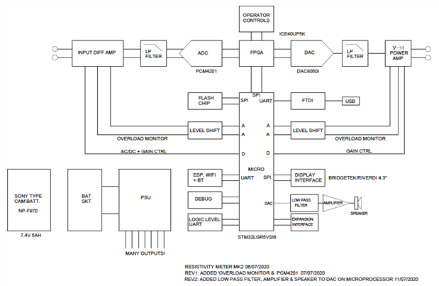
Hi I'm looking for ideas on an update to a resistivity meter for archaeology. The only published designs for diy were in 2 magazines. One was published in 1997 and the other in 2003. I have copies of both articles available. The reason behind this is the current high cost of available equipment, usually well beyond the reach of most archaeological groups. I've attached a basic block diagram. In the first magazine article the meter is very basic. It relied on the operators to write down the reading given as the survey was taken. Given that a normal survey grid is 20m x 20m and 1 reading is taken on every sq mtr there would be 400 readings to write down and then input into a program used to interpret the results. The later article is really an update to the first where a PIC has been added to record the readings. This again is prone to error, because eadings are taken manually by pressing a button.

I'm sure given the advances in electronics there must be better ways. 


image

  • Sign in to reply
  • Cancel

Top Replies

  • kltm
    kltm over 5 years ago in reply to michaelkellett +8
    Hi Michael This all sounds very interesting and encouraging. I see you have found the original article, the update is also on slideshare somewhere. I haven’t really thought much about cost, but as you…
  • michaelkellett
    michaelkellett over 5 years ago in reply to shabaz +7
    I can't live with that - I have to have symmetry The problem is that the Howland current pump doesn't constrain the voltage on the load at all when perfectly balanced - and my LTSpice model is unrealistically…
  • michaelkellett
    michaelkellett over 5 years ago in reply to michaelkellett +7
    AS promised - now for the phase sensitive detector. I couldn't easily model this in LTSpice, which is no great surprise because it needs multiplication and square roots. I used Simulink in MATLAB - which…
  • kltm
    kltm over 5 years ago in reply to shabaz

    image

    • Cancel
    • Vote Up +4 Vote Down
    • Sign in to reply
    • Cancel
  • michaelkellett
    michaelkellett over 5 years ago in reply to kltm

    Great.

    I think I'm ready to draw up schematics.

    (You might think a formal spec should come first  - but we have a lot of stuff in this thread already and I find

    that trying to make a a complete design often helps focus on issues that abstract planning misses.

    Think of it as an Agile approach to hardware design image And schematics are easily changed.)


    I'm wondering if we should start new threads or make a new group for this project.


    MK

    • Cancel
    • Vote Up +4 Vote Down
    • Sign in to reply
    • Cancel
  • shabaz
    shabaz over 5 years ago in reply to michaelkellett

    Hi Michael,

    Hehe by random coincidence I was reading last night that it's a valid approach, to have elements of architecture and design co-occurring like you intuitively suggest! it's ISO 42020.

    Regarding group/thread I've never created a group on the platform so I'm unsure how it works but sounds like the right thing. Maybe Dudley or cstanton can advise the best method for such a project.

    Also, either way if a tag is also used (e.g. some unique codename/project name) and it is added to the new content and to this old thread, then it can be conveniently grouped up by Jive perhaps (like with a custom banner and intro etc, or at least just searchable based on that tag).

    • Cancel
    • Vote Up +1 Vote Down
    • Sign in to reply
    • Cancel
  • Jan Cumps
    Jan Cumps over 5 years ago in reply to shabaz

    Another option is to create a Document. It can be maintained by several people and has versioning.

    You can set who has edit right.

    Editing it is identical as with a blog post.

    • Cancel
    • Vote Up +2 Vote Down
    • Sign in to reply
    • Cancel
  • davemartin
    davemartin over 5 years ago in reply to shabaz

    Shabaz,


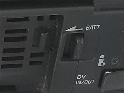
    That plate looks to lock on the side, that may well do. The other way which the Sony decks use is that you drop the battery onto the tray and slide it in to not only make contact but also the hooks engage with protrusions on the side, then there's a spring-loaded latch which pops-up and stops the battery sliding back so the hooks and contacts remain engaged. I haven't shopped for free NPF plates for a few years now, but I haven't seen any with the positive lock like the Sony GVD and similar decks:


    image


    Dave

    • Cancel
    • Vote Up +3 Vote Down
    • Sign in to reply
    • Cancel
  • davemartin
    davemartin over 5 years ago in reply to davemartin

    Power supply management:


    One aspect touched upon by Michael already is the need to have a pre-emptive shutdown to avoid over-discharging the battery pack, and I mentioned the need for plenty of warning to try and avoid having a break mid-grid.


    It is, I suspect, unlikely that it will be possible to take advantage of the intelligence built into some packs which tracks charge and allows predictions. As I was driving yesterday, the sight of the fuel consumption/prediction display in my car made me wonder if it might be possible to include something basic along the same lines, that could well bring a useful usability improvement in the field if the kit is constrained by its battery pack. The usability could not only be a ‘battery fuel gauge’ but, once one grid had been done, the geology and hence power consumption would be approximately known*, so at the end of one grid and before starting the next grid, the UI could pop up a message “You may not have enough battery left to complete the next grid” so the battery could be pre-emptively swapped or charged.


    * i.e. good noise-free conditions where you only needed 20mW (20v to get 1mA), or more challenging where you needed over half a watt (50-60v to get 10mA).


    Dave

    • Cancel
    • Vote Up +2 Vote Down
    • Sign in to reply
    • Cancel
  • michaelkellett
    michaelkellett over 5 years ago in reply to davemartin

    It's not too hard to measure the current drain from the battery. and its under load voltage. From the current we can estimate

    the drain from the battery since last swapped and from the voltage (and possibly ambient temperature) we can estimate (less accurately)

    how long the battery has left.

    It would be nice if the instrument could recognise individual batteries but I think this would be too difficult to get right.

    We do need a good way of telling when the battery has changed  - without some means added specifically to do this the instrument

    can't tell the difference between being switched off and the battery being removed.If operators insist on swapping a battery for a half charged

    one, we can't estimate its endurance other than by voltage.


    This means that we need a circuit that is always connected to the battery terminals and can indicate to the processor if the battery has been disconnected

    for more than (for example, 10 seconds). The processor can reset the circuit once it has reset its charge measuring system. The battery disconnect

    detect circuit should draw no more than 50uA from the battery when the instrument is off. (8% of a 5Ah battery per year.) It doesn't need to be very accurate,

    battery present voltage, > (4 - 5.5 V), battery absent, < (2 - 3.9 V), timing +/- 30%


    Suggestions welcome (simple and cheap is good)


    MK

    • Cancel
    • Vote Up +2 Vote Down
    • Sign in to reply
    • Cancel
  • shabaz
    shabaz over 5 years ago in reply to michaelkellett

    Hi Michael,


    Maybe an alternative could be for (say) a 4-bit switch (i.e. 16 values), or instead a PCB with scratch-off traces to be taped to the battery, with a plug on the end, to encode 15 or so batteries. Then the microcontroller can always know if a different battery is attached (writing to the microcontroller board existing NVRAM), but also always prompt the user (at power-on) to acknowledge the battery was not changed, if it detects that the same battery as before is connected (this message would therefore be rare for the user to see during the day, if the instrument is only switched off to change batteries, since a battery change to a different battery is auto-detected through the 4-bit input). The acknowledgement would only be needed on power reset if the same battery was detected.


    The four or so inputs could be useful for implementing different battery detection or measuring methods in the future, e.g. I2C EEPROM chip with a plug on the end too, or full I2C fuel gauge chip if the battery holder and battery were replaced in a future modification.


    Another way could be to allow an option with two batteries, OR'd, and then the microcontroller can always know if either was disconnected and re-inserted, by looking at the voltages on the battery side of the OR.

    Both the 4-bit input and the OR circuit are compromises, but have scope for future enhancements if a few I/O lines were left near the battery connections.


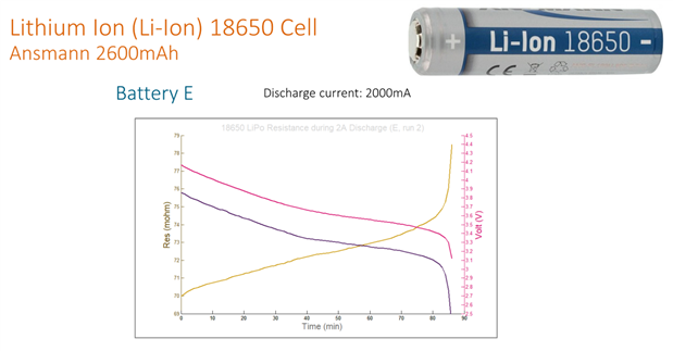
    Also, (just so no-one can patent it), going to put the idea of it self-measuring the battery impedance out there, using its existing circuitry. The DAC output could toggle a MOSFET to place a load on the device, at (say) 1kHz or any other frequency (square wave could be used for this test since sine-wave accuracy might not be needed), and relays or another method (could even be a manual switch) to connect the sense inputs to the circuit. This could be performed at power-on and in-between grids. It would easily detect the battery state being in the last (say) third of its charge state (experiments with a single 18650 in the diagram below, this was done during BA6010 review).

    image

    • Cancel
    • Vote Up +1 Vote Down
    • Sign in to reply
    • Cancel
  • michaelkellett
    michaelkellett over 5 years ago in reply to shabaz

    Hello Shabaz,


    While having individual battery ID would be nice it does seem a bit complex.

    \there will be connectorised spare IO on the pcb so add ons are possible.

    You would still need the battery out detector because the user might remove a battery then charge and replace it without turning the instrument on.

    We will measure battery voltage and current, from you graphs battery voltage is as good an indicator as battery impedance.


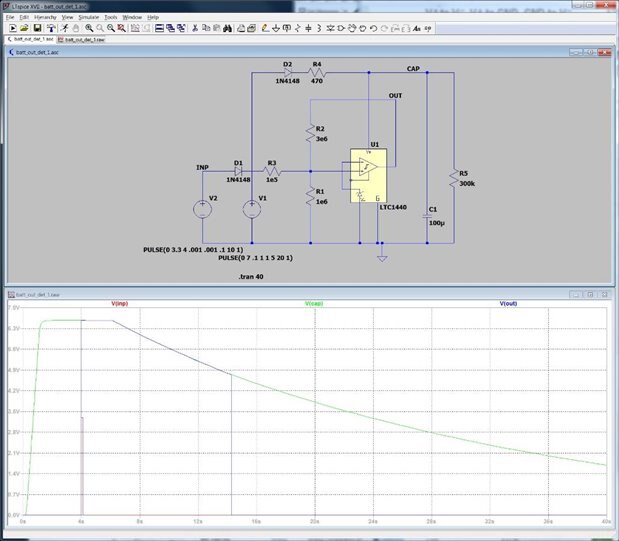
    I've come up with a battery out detector - draws about 30uA, mostly through R5.

    Seems OK in simulation.

    image

    AT 4 seconds, once the cap has charged up the pulse on INP sets the output of the comparator.  The hystereis via R2 will

    keep the cpmarator set until the supply voltage drops too low for R2 to keep the voltage at the positive input above the reference.

    The time between battery off and comparator supply low is set by C1 and R5. Most of the current (about 85%)  flows though R5,

    but 30uA is quite good enough. You can fiddle around and get to less than half that (C1  to 47u, R5 to 750k, but the timing

    will be more variable with comparator current.)


    MK

    • Cancel
    • Vote Up +2 Vote Down
    • Sign in to reply
    • Cancel
  • cstanton
    cstanton over 5 years ago in reply to shabaz

    If there's a good reason for a group to be made then I can help that to happen.

    If the problem is trying to trawl through this entire thread, then there's an URL you can use which helps to display all of the comments, and that is Archaeology Resistivity Meter where ?displayFullThread=true is at the end of the URL.


    • Cancel
    • Vote Up +4 Vote Down
    • Sign in to reply
    • Cancel
<>
element14 Community

element14 is the first online community specifically for engineers. Connect with your peers and get expert answers to your questions.

  • Members
  • Learn
  • Technologies
  • Challenges & Projects
  • Products
  • Store
  • About Us
  • Feedback & Support
  • FAQs
  • Terms of Use
  • Privacy Policy
  • Legal and Copyright Notices
  • Sitemap
  • Cookies

An Avnet Company © 2025 Premier Farnell Limited. All Rights Reserved.

Premier Farnell Ltd, registered in England and Wales (no 00876412), registered office: Farnell House, Forge Lane, Leeds LS12 2NE.

ICP 备案号 10220084.

Follow element14

  • X
  • Facebook
  • linkedin
  • YouTube