element14 Community
element14 Community
    Register Log In
  • Site
  • Search
  • Log In Register
  • Community Hub
    Community Hub
    • What's New on element14
    • Feedback and Support
    • Benefits of Membership
    • Personal Blogs
    • Members Area
    • Achievement Levels
  • Learn
    Learn
    • Ask an Expert
    • eBooks
    • element14 presents
    • Learning Center
    • Tech Spotlight
    • STEM Academy
    • Webinars, Training and Events
    • Learning Groups
  • Technologies
    Technologies
    • 3D Printing
    • FPGA
    • Industrial Automation
    • Internet of Things
    • Power & Energy
    • Sensors
    • Technology Groups
  • Challenges & Projects
    Challenges & Projects
    • Design Challenges
    • element14 presents Projects
    • Project14
    • Arduino Projects
    • Raspberry Pi Projects
    • Project Groups
  • Products
    Products
    • Arduino
    • Avnet & Tria Boards Community
    • Dev Tools
    • Manufacturers
    • Multicomp Pro
    • Product Groups
    • Raspberry Pi
    • RoadTests & Reviews
  • About Us
  • Store
    Store
    • Visit Your Store
    • Choose another store...
      • Europe
      •  Austria (German)
      •  Belgium (Dutch, French)
      •  Bulgaria (Bulgarian)
      •  Czech Republic (Czech)
      •  Denmark (Danish)
      •  Estonia (Estonian)
      •  Finland (Finnish)
      •  France (French)
      •  Germany (German)
      •  Hungary (Hungarian)
      •  Ireland
      •  Israel
      •  Italy (Italian)
      •  Latvia (Latvian)
      •  
      •  Lithuania (Lithuanian)
      •  Netherlands (Dutch)
      •  Norway (Norwegian)
      •  Poland (Polish)
      •  Portugal (Portuguese)
      •  Romania (Romanian)
      •  Russia (Russian)
      •  Slovakia (Slovak)
      •  Slovenia (Slovenian)
      •  Spain (Spanish)
      •  Sweden (Swedish)
      •  Switzerland(German, French)
      •  Turkey (Turkish)
      •  United Kingdom
      • Asia Pacific
      •  Australia
      •  China
      •  Hong Kong
      •  India
      •  Korea (Korean)
      •  Malaysia
      •  New Zealand
      •  Philippines
      •  Singapore
      •  Taiwan
      •  Thailand (Thai)
      • Americas
      •  Brazil (Portuguese)
      •  Canada
      •  Mexico (Spanish)
      •  United States
      Can't find the country/region you're looking for? Visit our export site or find a local distributor.
  • Translate
  • Profile
  • Settings
Open Source Hardware
  • Technologies
  • More
Open Source Hardware
Forum Help sought in evaluating pcb design
  • Blog
  • Forum
  • Documents
  • Events
  • Polls
  • Members
  • Mentions
  • Sub-Groups
  • Tags
  • More
  • Cancel
  • New
Join Open Source Hardware to participate - click to join for free!
Actions
  • Share
  • More
  • Cancel
Forum Thread Details
  • Replies 7 replies
  • Subscribers 318 subscribers
  • Views 633 views
  • Users 0 members are here
Related

Help sought in evaluating pcb design

Former Member
Former Member over 15 years ago

Hi,


I'm a pcb-design newbie and I just finished designing one of my first pcb boards in Eagle. The design passed all the rule checks - but I want to make sure it will be OK when it arrives. Can anyone help me evaluate my design before I send this to the fab?


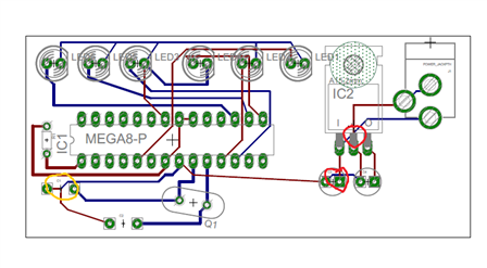
It's a basic design, where I use an Atmega 328 (along with its required voltage regulator, capacitors, etc.) and a series of LEDs I use to light up like the car from Knight Rider.


PDFs of my board and schematic are attached. Thanks, in advance, for all your help.

Attachments:
imagecylonschem.pdf
imagecylon.pdf
  • Sign in to reply
  • Cancel
Parents
  • ChrisDancer
    ChrisDancer over 15 years ago

    Hi John,


    The circuit:


    You don't need a big 1A regulator. I would use a TO92 type like the 78L05 (assuming it's 5V)


    Do not assume that the two ground pins on the IC are internally connected. Connect them both to ground with tracks. Even if they are connected internally, what you are doing is running the current for all your LEDs through the tiny wires inside the IC. That's not good practice.


    Put a ceramic 100nF decoupling capacitor across the power pins of the IC. The electrolytic caps on the regulator don't work well at high frequencies.


    The schematic:


    Basically OK but why is R1 flapping about down there?


    The board:


    My eyes! My eyes!image


    Thicken your tracks! If there's one thing that drives me crazy it's needle-thin tracks snaking across empty space on a board.


    Really thicken your power and ground tracks. It's also a good idea to fill empty space with copper connected to ground. It reduces the resistance between points connected to ground, which helps to eliminate ground noise, and it acts as an electrical screen.


    Where you have something that is subject to movement like a connector or switch, make the copper it is attached to nice and big. The copper is what is holding the thing in place. Small pads will eventually break loose or develop hairline cracks which are a swine to find.


    The crystal and its caps should be as close to the IC as possible. As should that decoupling cap I mentioned.


    Aesthetically it's nice if things are aligned to the vertical and the horizontal! Tracks should be vertical, horizontal or 45 degrees. Avoid right-angle bends in tracks except where you can't avoid them, such as T junctions; instead use a 45 degree mitred corner.


    Apart from all that, it's great!


    Chris

    • Cancel
    • Vote Up 0 Vote Down
    • Sign in to reply
    • Cancel
Reply
  • ChrisDancer
    ChrisDancer over 15 years ago

    Hi John,


    The circuit:


    You don't need a big 1A regulator. I would use a TO92 type like the 78L05 (assuming it's 5V)


    Do not assume that the two ground pins on the IC are internally connected. Connect them both to ground with tracks. Even if they are connected internally, what you are doing is running the current for all your LEDs through the tiny wires inside the IC. That's not good practice.


    Put a ceramic 100nF decoupling capacitor across the power pins of the IC. The electrolytic caps on the regulator don't work well at high frequencies.


    The schematic:


    Basically OK but why is R1 flapping about down there?


    The board:


    My eyes! My eyes!image


    Thicken your tracks! If there's one thing that drives me crazy it's needle-thin tracks snaking across empty space on a board.


    Really thicken your power and ground tracks. It's also a good idea to fill empty space with copper connected to ground. It reduces the resistance between points connected to ground, which helps to eliminate ground noise, and it acts as an electrical screen.


    Where you have something that is subject to movement like a connector or switch, make the copper it is attached to nice and big. The copper is what is holding the thing in place. Small pads will eventually break loose or develop hairline cracks which are a swine to find.


    The crystal and its caps should be as close to the IC as possible. As should that decoupling cap I mentioned.


    Aesthetically it's nice if things are aligned to the vertical and the horizontal! Tracks should be vertical, horizontal or 45 degrees. Avoid right-angle bends in tracks except where you can't avoid them, such as T junctions; instead use a 45 degree mitred corner.


    Apart from all that, it's great!


    Chris

    • Cancel
    • Vote Up 0 Vote Down
    • Sign in to reply
    • Cancel
Children
  • Former Member
    Former Member over 15 years ago in reply to ChrisDancer

    Chris,


    Thanks for taking the time to critique my work!! I am a newbie and I guess it shows. I will incorporate your suggestions!


    By the way, where do you source your parts. I am new at knowing where to go and get things like smd resisotrs, etc?


    Thanks again!!!

    • Cancel
    • Vote Up 0 Vote Down
    • Sign in to reply
    • Cancel
  • Former Member
    Former Member over 15 years ago in reply to Former Member

    There are some other problems Chris didn't mention. Yes it does show that this is your first board but you should not be ashamed of that in any way, everyone has to start somewhere, and this board is simple enough to learn the fundamentals. I have uploaded an image below that will help illustrate my points.


    1. There are some traces that are too close to pads for my taste. The red circled areas in the picture below show what I'm talking about. They may have passed DRC but it's just not good practice to have traces that close to pads if you have the room to maneuver. Always remember that a green pad or via will have exposed copper on BOTH sides of the board, so both red and blue traces need to avoid the pads/vias.


    2. The orange circle shows a place that is not right. Basically, the blue trace is not connected to anything! There is no via to make a connection between the red and blue traces right there, so the blue trace will not connect to anything on that side of the board, unless there is some kind of hidden trace that I can't see in the image. It looks to me like there used to be a via there and you accidentally deleted it.


    3. Q1 is rotated very oddly. Avoid that at all costs. As Chris said, you want everything aligned vertically or horizontally on the board (and in some cases 45 degrees is ok). This is pretty easy to do if you adjust the grid size/alternate size in Eagle. Usually for a simple board like this I would just route the board on a .1 in. grid with .05 in. alternate grid spacing.


    4. You almost never want traces that have 90 degree bends in them. This can cause connection issues and possibly even trace lifting since the trace is changing direction so sharply. Avoid at all costs unless it's the only thing you can do. Instead use the built in 45-degree route tool to automatically bend the trace 45 degrees when you want to change direction. This will also make your design look pretty (which never hurts!). Generally a rule I go by is you always want solid trace lines, with no "jaggies" that are the result of a weird diagonal. The red trace going from the micro to C3 is an example of this.


    5. I agree that you don't need a large regulator for such a small board, so a TO-220 package is overkill, assuming that's what it is. Also, the real part will tend to take up more space then the outline you see on the silkscreen layer, so it is very possible when you get the board that the part hangs off the edge of the board.


    6. On LED3 there is a really bad angled connection on what looks like the anode. Definitely fix that, 90 degree turns aren't good but that's definitely not good.


    7. To make things look better aesthetically, try making traces evenly spaced, so you don't have several traces bunched up, and then a large gap of nothing, and then more traces. Also, you can really shrink the board space here, because you have a TON of unused real-estate. I would move the micro more to the left, rotate the regulator and power jack 90 degrees and move them to the left, move the crystal more to the left, and fix the LED spacing. This will allow you to make your board much smaller and thus, save a lot of money.


    As for part sourcing, Digikey and Mouser are your best friends!


    image

    • Cancel
    • Vote Up 0 Vote Down
    • Sign in to reply
    • Cancel
  • ChrisDancer
    ChrisDancer over 15 years ago in reply to Former Member

    "By the way, where do you source your parts."


    I'm in the UK so the shipping fees may be quite high! In the US, Digi-key, Mouser and Jameco are all good. For building up a general stock of parts Ebay is a good source. I bought some kits of SMD resistors from an Ebay shop which were very cheap and have been really useful. Sometimes you can pick up some weird and wonderful parts too.

    When designing with SMD resistors and capacitors it's a good idea to standardise on one size. I use 1206 because it is the biggest and the easiest to hand-solder.

    • Cancel
    • Vote Up 0 Vote Down
    • Sign in to reply
    • Cancel
  • Former Member
    Former Member over 15 years ago in reply to ChrisDancer

    I agree about the ebay tip and the bulk SMD's. However, 1206 are rather large, so if you're working with tight designs they're pretty unwieldy. I think 0805 is a much better "standard" size for DIY projects because they take up much less space and it's still pretty easy to solder them by hand. I use almost all 0603 myself but I'm used to soldering small SMT packages.

    • Cancel
    • Vote Up 0 Vote Down
    • Sign in to reply
    • Cancel
element14 Community

element14 is the first online community specifically for engineers. Connect with your peers and get expert answers to your questions.

  • Members
  • Learn
  • Technologies
  • Challenges & Projects
  • Products
  • Store
  • About Us
  • Feedback & Support
  • FAQs
  • Terms of Use
  • Privacy Policy
  • Legal and Copyright Notices
  • Sitemap
  • Cookies

An Avnet Company © 2025 Premier Farnell Limited. All Rights Reserved.

Premier Farnell Ltd, registered in England and Wales (no 00876412), registered office: Farnell House, Forge Lane, Leeds LS12 2NE.

ICP 备案号 10220084.

Follow element14

  • X
  • Facebook
  • linkedin
  • YouTube