


Hello Everyone!
I am going to build a DIY bench power supply. I have decided to build a dual supply based on the schematic below.
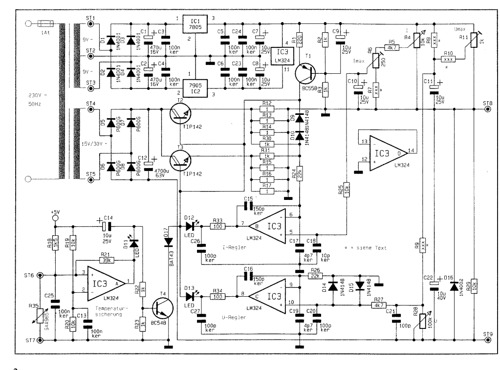
Here is the full pdf...http://www.elv-downloads.de/Assets/Produkte/2/225/22532/Downloads/22532_Universelle_Netzteilplatine_um.pdf
I have a couple of questions regarding this design. According to the description(translated), by selecting some resistor values, I can either build a 0-15V 4A supply, or a 0-30V 2A supply. Why is the 30V version limited to 2A? If it is not possible to build a 0-30V 4A design, which version would be more useful? I am beginning to learn electronics, but know that I will want to deal with motors, robotics, audio circuits, etc...
To build a dual supply, will I also have to have two transformers? I will want to be able to connect them in series, and in parallel, so I know they have to be isolated from each other. What kind of transformer do I need? When searching for transformer on digikey, I do not know what I need enough to filter the results.
On the bottom left, there is some form of temperature measurement using a 'SAA965' which is actually a KTY81-151. - Datasheet: [url]http://www.datasheetcatalog.org/datasheet/philips/KTY81-151.pdf[/url]
What do I use this to measure the temperature of? The heat sink of the transistor? How do I attach it to what ever I am measuring? Also in the area of the temperature measurement, there is a 5V supply. Where is the 5V supply coming from, the 7805 at the top? And what are the the two lines coming out to the left, labeled 'ST6' & 'ST7' going to?
I will want to have panel meters displaying voltage and current output. I think I want to incorporate possibly a uC into the project, for some 'fanciness' I have in mind, once I have the foundation, so maybe just a LCD is all I need. For the Panel meter, and micro ideas, can I use the 5V supply, that is also the 5V supply for the LM324, or will I need another small transformer, to power these items?
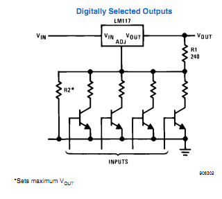
Some people suggested in another thread, that I use a ten turn pot on my supply. I also agree that that is a good idea. In the LM317 datasheet, there is an example(below) about digitally selected outputs. Would this also work on this supply? I think I want a button for 5 and 3.3 volts, and the micro will select the correct resistance. What are the downsides of this?
Some people have mentioned a 'load switch.' Is that just a normal toggle switch(that can handle the current), to just quickly disconnect the output? Would a beefy switch, or a small switch with a relay be better?
What are the funny looking pots in the top right of the schematic? Why do they have a flat end, instead of an arrow-does this represent something significant?
One last question: What are the transistors with two lines coming out of them? What do the two lines represent?
My goal is to have a nice dual supply, that I can use for years as I continue to learn about electronics. I will greatly appreciate any advice, answers to questions, or just ideas I haven't thought about. Also, some of the above information is not 'set in stone'. I.E. if it is better to use a different design for the supply, than I am willing to use that one instead.
Thanks in advance,
Joshua

