element14 Community
element14 Community
    Register Log In
  • Site
  • Search
  • Log In Register
  • Community Hub
    Community Hub
    • What's New on element14
    • Feedback and Support
    • Benefits of Membership
    • Personal Blogs
    • Members Area
    • Achievement Levels
  • Learn
    Learn
    • Ask an Expert
    • eBooks
    • element14 presents
    • Learning Center
    • Tech Spotlight
    • STEM Academy
    • Webinars, Training and Events
    • Learning Groups
  • Technologies
    Technologies
    • 3D Printing
    • FPGA
    • Industrial Automation
    • Internet of Things
    • Power & Energy
    • Sensors
    • Technology Groups
  • Challenges & Projects
    Challenges & Projects
    • Design Challenges
    • element14 presents Projects
    • Project14
    • Arduino Projects
    • Raspberry Pi Projects
    • Project Groups
  • Products
    Products
    • Arduino
    • Avnet & Tria Boards Community
    • Dev Tools
    • Manufacturers
    • Multicomp Pro
    • Product Groups
    • Raspberry Pi
    • RoadTests & Reviews
  • About Us
  • Store
    Store
    • Visit Your Store
    • Choose another store...
      • Europe
      •  Austria (German)
      •  Belgium (Dutch, French)
      •  Bulgaria (Bulgarian)
      •  Czech Republic (Czech)
      •  Denmark (Danish)
      •  Estonia (Estonian)
      •  Finland (Finnish)
      •  France (French)
      •  Germany (German)
      •  Hungary (Hungarian)
      •  Ireland
      •  Israel
      •  Italy (Italian)
      •  Latvia (Latvian)
      •  
      •  Lithuania (Lithuanian)
      •  Netherlands (Dutch)
      •  Norway (Norwegian)
      •  Poland (Polish)
      •  Portugal (Portuguese)
      •  Romania (Romanian)
      •  Russia (Russian)
      •  Slovakia (Slovak)
      •  Slovenia (Slovenian)
      •  Spain (Spanish)
      •  Sweden (Swedish)
      •  Switzerland(German, French)
      •  Turkey (Turkish)
      •  United Kingdom
      • Asia Pacific
      •  Australia
      •  China
      •  Hong Kong
      •  India
      •  Korea (Korean)
      •  Malaysia
      •  New Zealand
      •  Philippines
      •  Singapore
      •  Taiwan
      •  Thailand (Thai)
      • Americas
      •  Brazil (Portuguese)
      •  Canada
      •  Mexico (Spanish)
      •  United States
      Can't find the country/region you're looking for? Visit our export site or find a local distributor.
  • Translate
  • Profile
  • Settings
Open Source Hardware
  • Technologies
  • More
Open Source Hardware
Forum 555 Timer Rapid Flashing
  • Blog
  • Forum
  • Documents
  • Events
  • Polls
  • Members
  • Mentions
  • Sub-Groups
  • Tags
  • More
  • Cancel
  • New
Join Open Source Hardware to participate - click to join for free!
Actions
  • Share
  • More
  • Cancel
Forum Thread Details
  • State Verified Answer
  • Replies 25 replies
  • Answers 2 answers
  • Subscribers 320 subscribers
  • Views 3121 views
  • Users 0 members are here
  • 555_timer
  • blink
Related

555 Timer Rapid Flashing

Former Member
Former Member over 10 years ago

Hey everyone.


I've been trying to use a 555 timer in one of my projects but I'm not sure how.

I've never used one before so I'm not sure if when I'm using it I'm setting up the circuit wrong or the chip is broken.


If you guys could help me, I'm just trying to make a rapid blinking circuit.


NOTE: My end goal is to have the output blink rapidly while a button is being pressed and do nothing when it's not. If there is a better way to do this than a 555 timer, please let me know.


Thanks.


P.S. I know this isn't really in the right section but it was the closest I could find.

  • Sign in to reply
  • Cancel

Top Replies

  • balearicdynamics
    balearicdynamics over 10 years ago +2
    Kartin I already saw in past the 555 is great in association with Arduino. If you need let me know I have collected for some experiments a lot of e-books and documentation on 555 circuit schemes most of…
  • mcb1
    mcb1 over 10 years ago +1
    Kartin Yes Arduino isn't quite the right place, and the list above doesn't give the full range element14jamie might have a better place .... Firstly you might need to give a clue about what schematic you…
  • clem57
    clem57 over 10 years ago +1 verified
    50 - 555 Circuits 555 Delay Times: C R 1 = 100k R 2 = 100k R 1 = 470k R 2 = 470k R 1 = 1M R 2 = 1M 10µ 2.2sec 10 sec 22sec 100 µ 22sec 10 0sec 220sec 470 µ 100sec 50 0sec 1000sec So the best you can do…
Parents
  • clem57
    0 clem57 over 10 years ago

    image

    50 - 555 Circuits


    555 Delay Times:
    CR1 = 100k
    R2 = 100k
    R1 = 470k
    R2 = 470k
    R1 = 1M
    R2 = 1M
    10µ2.2sec10sec22sec
    100µ22sec100sec220sec
    470µ100sec500sec1000sec


    So the best you can do is 2.2 secs with the corner above. Bad news is the circuit uses power at 10mA.

    • Cancel
    • Vote Up +1 Vote Down
    • Sign in to reply
    • Reject Answer
    • Cancel
  • Former Member
    0 Former Member over 10 years ago in reply to clem57

    Thank you very much. I will definetly try with that circuit.


    Here is the circuit I was originally trying that didn't seem to work:

    Schematic.png


    The only thing I did differently was I used a 100K resistor for R2 instead of a 470K because I didn't have a 470K.

    I didn't think that would make a huge different, but I'm not an expert on 555 timers because I've never used one before.


    Thanks for all the good advice. I try again with the suggested circuit and see if it works.

    • Cancel
    • Vote Up 0 Vote Down
    • Sign in to reply
    • Verify Answer
    • Cancel
  • clem57
    0 clem57 over 10 years ago in reply to Former Member

    Pin 3 is output and the LED looks backward. Also the LED should go to gnd.

    • Cancel
    • Vote Up 0 Vote Down
    • Sign in to reply
    • Verify Answer
    • Reject Answer
    • Cancel
  • mcb1
    0 mcb1 over 10 years ago in reply to clem57

    Pin 3 is output

    I think you'll find Pin3 is a digital output, so it should go low when in the OFF state.

    http://www.555-timer-circuits.com/using-the-output.html


    I see nothing wrong with your schematic.

    What is the value of C1, and if it is an electrolytic did you have the - side to ground ?


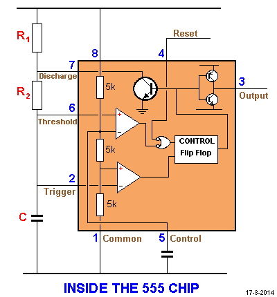
    It is worth adding a 1nF or similar across pin 5 to ground ... think of it as insurance.

    For any digital circuit it is always a good idea to add a 470uF -1000uF capacitor PLUS a 100nF (0.1uF) across the supply rails close to the chip to stop the spikes causing unwanted issues.


    Mark

    • Cancel
    • Vote Up 0 Vote Down
    • Sign in to reply
    • Verify Answer
    • Reject Answer
    • Cancel
  • Former Member
    0 Former Member over 10 years ago in reply to mcb1

    The schematic I found on some website with a little bit of instructions but they didn't give a value for C1.

    So I put in a 100uF capacitor (I don't think it was electrolytic) because that was what I had a easiest access.

    • Cancel
    • Vote Up 0 Vote Down
    • Sign in to reply
    • Verify Answer
    • Cancel
  • mcb1
    0 mcb1 over 10 years ago in reply to Former Member

    So I put in a 100uF capacitor

    100uF will be a polarised capacitor of some type.

    Double check you have it the correct way, and if possible change it just in case it is leaky.  image


    If you do the calculation that was supplied earlier it runs at 0.0153Hz

    http://www.daycounter.com/Calculators/NE555-Calculator.phtml

    image


    or from here http://web.udl.es/usuaris/p7806757/555-calculadora/555%20Calculator.htm

    image

    It is ON or Off for 32 secs.


    so you can see how useful the 265 million hits are to resolving why it might not work the way you planned.


    Mark

    • Cancel
    • Vote Up 0 Vote Down
    • Sign in to reply
    • Verify Answer
    • Cancel
  • Former Member
    0 Former Member over 10 years ago in reply to mcb1

    Thanks.


    I did try the capacitor both ways but I may not have waited 32 seconds, so my problem might have been caused by impatience though I believe I left it for long enough.


    I'll try again and see if it works once I have time.

    • Cancel
    • Vote Up 0 Vote Down
    • Sign in to reply
    • Verify Answer
    • Cancel
Reply
  • Former Member
    0 Former Member over 10 years ago in reply to mcb1

    Thanks.


    I did try the capacitor both ways but I may not have waited 32 seconds, so my problem might have been caused by impatience though I believe I left it for long enough.


    I'll try again and see if it works once I have time.

    • Cancel
    • Vote Up 0 Vote Down
    • Sign in to reply
    • Verify Answer
    • Cancel
Children
  • mcb1
    0 mcb1 over 10 years ago in reply to Former Member

    I did try the capacitor both ways but I may not have waited 32 seconds

    It is a long time when you think it should flash rapidly. ...image


    The lack of capacitor across Pin5 could also increase the time by a factor of 10...


    If you try different values for R2 in the second link, swapping the 470k for 12k gets you a 0.9Hz flash.

    You can always add a 12k across the 470 to try it ...it will check your circuit does work.


    Mark

    • Cancel
    • Vote Up 0 Vote Down
    • Sign in to reply
    • Verify Answer
    • Cancel
  • Former Member
    0 Former Member over 10 years ago in reply to mcb1

    Thank you guys so much.


    I tried Clem Martins Circuit and it work exactly as it was supposed to.

    I don't know what I was doing wrong originally (I think it was the pin 5 control wasn't hooked up right, but I don't know) but it works now.


    Thank you all so much. I thought I was doomed to never have an IC work for me because a have a couple of and, not, and or gates, but I couldn't get them to work either (but that is a problem for another time).


    Again, Thank you all.

    • Cancel
    • Vote Up 0 Vote Down
    • Sign in to reply
    • Verify Answer
    • Cancel
  • mcb1
    0 mcb1 over 10 years ago in reply to Former Member

    That's great you sorted it, and learnt something along the way ...image


    Perhaps you could mark Clem's answer correct and any others you want as helpful.


    Mark

    • Cancel
    • Vote Up +1 Vote Down
    • Sign in to reply
    • Verify Answer
    • Cancel
element14 Community

element14 is the first online community specifically for engineers. Connect with your peers and get expert answers to your questions.

  • Members
  • Learn
  • Technologies
  • Challenges & Projects
  • Products
  • Store
  • About Us
  • Feedback & Support
  • FAQs
  • Terms of Use
  • Privacy Policy
  • Legal and Copyright Notices
  • Sitemap
  • Cookies

An Avnet Company © 2025 Premier Farnell Limited. All Rights Reserved.

Premier Farnell Ltd, registered in England and Wales (no 00876412), registered office: Farnell House, Forge Lane, Leeds LS12 2NE.

ICP 备案号 10220084.

Follow element14

  • X
  • Facebook
  • linkedin
  • YouTube