


Introduction
I'm having a bit of fun experimenting. With capacitor leakage. It's all a bit ad hoc and Heath Robinson-
ish, and I'm probably setting a very bad example of how to go about engineering, but never mind. As long
as you just read it out of interest and keep saying to yourself 'why doesn't he do it properly?' or
'that's a useless way to do things, I can think of a much better way', we'll be fine. I'm doing this with
fairly minimal test equipment - just a fairly average 200MHz 'scope (a Tektronix MSO2022A) and a 5.5 digit
bench multimeter (a Fluke 8808A) - because that's all I've got; but it's always surprising what can be
done with even the simplest of gear. I'm not going to be working to great precision - the idea is to take
a qualitative look at what's going on rather than go for accurate measurements.
I know very little about the inner world of capacitors or, perhaps a bit more accurately given the theme
of the current blog, the various dielectrics that you'll find between the plates of capacitors. Most of
what I know is largely design advice I've picked up along the way - things like, taking into account the
bias voltage on a MLCC because of the way it reduces the capacitance, and stuff like that - without much
awareness of the actual physics involved. That means I'm not going to be teaching you anything; this is
purely exploratory and experimental.
The Circuit
The first configuration I considered was this

I tried building a circuit along those lines but had problems getting it stable.
This is the circuit configuration I went with in the end
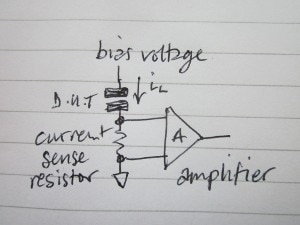
simply pass the leakage current through a resistor and amplify the voltage difference between the ends.
Whatever the device is that does the amplification, it needs to have very low bias currents or the
currents into or out of the inputs will affect the reading. I don't have any instrumentation amplifiers
with those kinds of specs but I do have a LMC440 quad op amp with bias currents of only a few fA (!), so
I'm going to try making an instrumentation amplifier from that. The input offset voltage spec isn't all
that good, but for a one-off I could trim that out if it looked like being a problem.
For the current sense, I'm going to use a 10M resistor. That's a bit of a compromise. The value is
somewhat high for the larger possible leakage currents (up towards the uA area) and if I were doing this
again I might choose 1M and have a bit more gain on the amplifier.
There are various ways to make instrumentation amplifiers from op amps, but a favourite configuration is
often this one using three amplifiers
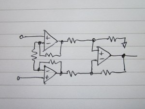
It's not too difficult to understand how it works. The output op amp is configured as a differential
amplifier. The input resistance isn't very high because of the resistors, so they are buffered by a pair
of voltage followers. Although they could literally be followers, that leads to a problem because to
change the gain would require varying two resistors at the same time in the differential amplifier.
Instead, the input pair are configured to be non-inverting with some gain [for overall unity gain, that
front-end gain can be compensated for by having a fractional gain on the differential stage]. Although
it's not immediately obvious, the lower gain setting resistors, which would normally both go to ground,
can be released from ground and simply joined together because of the symmetry of it's being a
differential amplifier, and that then leads to having one composite resistor that changes the gain of both
input amplifiers simultaneously [I'd nominate the person who thought of that for a 'Top Designer' badge,
except I don't know who it was].
Here's the detail of the test circuit I eventually ended up with.
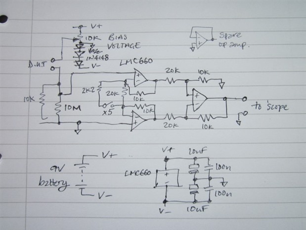
I don't know if it was really necessary but I decided to run the whole thing off a 9V battery. That should
keep the sensitive part fairly quiet. Going for 9V allows for a reasonable range on the bias voltage and
the batteries are fairly cheap. To get a negative rail, I simply lifted the ground by three diode drops
above the battery negative. That gives me rails of about +7.2V and -1.8V on a fresh battery. Because of
that battery, it's all floating and so the arrangement won't affect connecting the output to the
oscilloscope in any way. [Note that the LMC660 can operate with a supply up to +15V. This circuit wouldn't
be safe if you were to substitute a more modern CMOS op amp designed to run on no more than 5V or 6V,
unless you were to adapt it a bit.]
The switch and resistor allow me to change the gain from x1 to x5. I originally intended it to be x10, but
got it wrong. (Changing the 20k to 2k by adding the 2.2k in parallel doesn't change the gain by 10, as I
thought it might.)
Here's the circuit as I built it on a piece of bare copper-clad board.
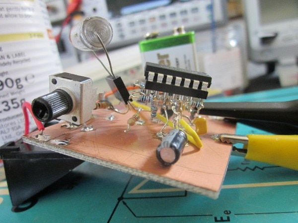
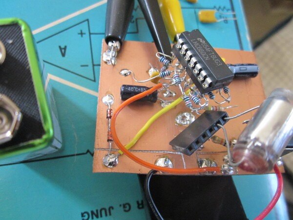
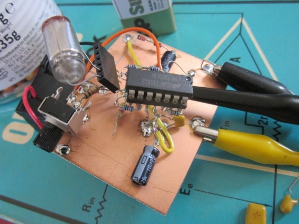
The odd arrangement with the 10k resistor, that has one end not soldered, is so that I can charge the
capacitor much more quickly than the 10M allows for. Pushing the free end down to the grounded copper
completes the circuit and the charging occurs about a thousand times quicker.
Here's the switched gain that I added after the other photographs were taken.

The reason that there are so many resistors around the pins of the IC socket is that I had plenty of small
1% 10k resistors, so I made the 20k ones from pairs of 10k in series.
The battery holder is underneath.
The capacitor you can see in the holder is one of the ones I was testing. It's a huge, old polystyrene
part made by winding two lengths of foil along with intermediate films of polystyrene and then heating it
so that it fuses together.
Doing some tests
When I came to try it, I immediately discovered that it would readily pick up noise, so I improvised an
electrostatic shield using a tin can from the kitchen.
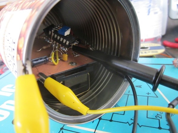
The yellow lead connects the ground on the circuit board to the can. I did think I might need a complete
enclosure, but pushing the board back into the can was enough. Much to my delight, after I had done it I
noticed that the can, which had originally held green lentils, had "Robust and Earthy" written on the
side.
220nF leaded MLCC
First off I tried an MLCC [multi-layer ceramic capacitor] part.
This took a long time to settle down, but eventually the leakage ended up right down near the bottom of my
measurement range. A major problem with these measurements is that initially you are looking at the
charging currents. Then there seems to be a period where the leakage is settling down, until finally it
all levels out. Having the 10k to speed up the discharge helped, but it still took time after that.
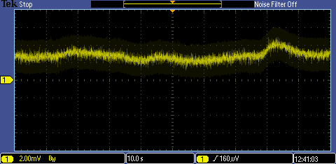
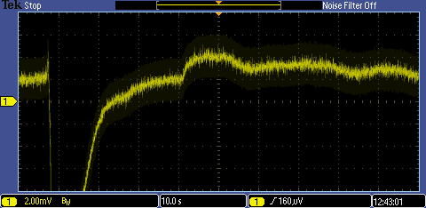
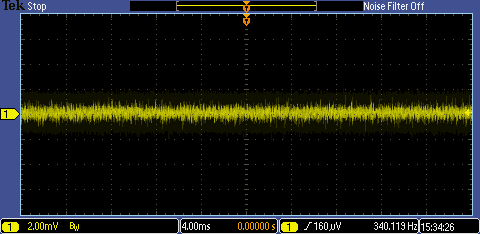
This is with the gain switched to x5, so the vertical scale is equivalent to 40pA/div. Bear in mind that
this is an improvised instrumentation amplifier and the voltage offset isn't too good - it measures around
0.5mV - so this really isn't precision stuff. The temperature was about 25C (a hot summer's day for where
I am in the UK) and the bias voltage applied was set to +5V.
The noise on the leakage current isn't very high at all. The trace noise is very similar in level with
both the x1 and the x5 settings, so it must emanate from the amplifier, the oscilloscope, and coupled
noise rather than the capacitor.
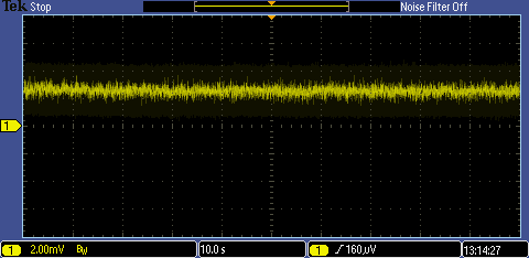
At first glance, it looks like the leakage is wandering around, but there's something else going on. Have
a look at this next trace
That's what happens if I breathe into the tin can and suddenly change the temperature. That can't (just)
be the leakage changing because the current changes direction, so I would think it's the actual
capacitance changing, because of the dimensional changes with temperature, resulting in a discharge
current to accommodate the change. So the wandering around in the first trace is probably air currents
affecting it as I move around and not anything inherent in the leakage.
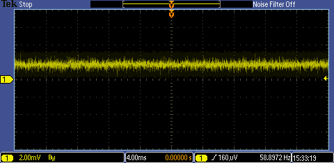
Here's the first trace done again with a paper tent over the whole thing to stop air moving in and out of
the can. This time the leakage current is much more steady. These thermal effects go on for a considerable
time - for this trace, I had to wait for several minutes before getting a nice steady trace after applying
the tent.
From that one, it looks like the final figure might be somewhere around 55pA (give or take a few tens of pA).
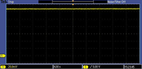
10uF 25V Electrolytic
This is on a gain of x1, so each division of 20mV represents 2nA. The reading of 12.8nA is higher than for
the MLCC, but is much, much better than I would have expected.
3.3uF 16V tantalum bead
Again a gain of one. This time about 200pA per division, so perhaps 160pA for the leakage. That's only
three times the MLCC figure. Again, much better than I would have expected.
Polystyrene
Here's an old polystyrene capacitor that I found. The leakage on this one was too low for me to measure
sensibly with this test setup.
Interestingly, the polystyrene part reacted slightly to the breathe test. As with the electrolytic, that
might well be down to dimensional changes modifying the capacitance rather than a change in the leakage,
though if so it goes in the opposite direction to the electrolytic with an immediate charge current rather
than a discharge current.

How does the bias voltage relate to leakage?
I'm going to go back to the electrolytic, as that has a reasonably high leakage that I can measure
sensibly, and try it at a few different bias voltages. There is going to be a relationship between the
voltage and the leakage current of some sort, because the potential difference is driving the current, but
does the leakage look like a simple resistance where the two are in proportion?
Here are the results for 1V to 5V in 1V steps. (I haven't suddenly acquired a 5-channel oscilloscope,
instead I composited the images together with Gimp.)
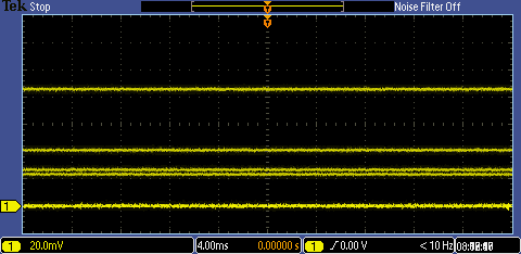
They go in order, 1V bias is the lowest and 5V bias the highest. The 5V reading is now different to what I
had yesterday (this time it's reading about 8.5pA, rather than the 12pA I got then), but this series was
taken in succession, using the same procedure each time, so should be indicative. It's quite obvious that
the relationship between voltage and leakage is very non-linear and, for an electrolytic capacitor, we
can't refer to a 'leakage resistance' in any meaningful way.
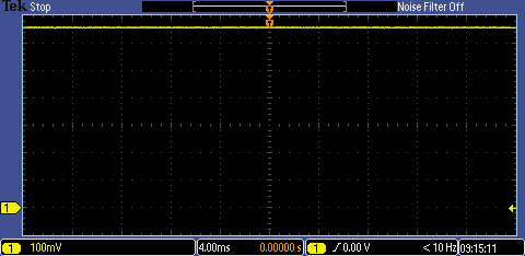
Just to emphasise that, here's the trace for a nominal 6V (note the change of scale). All of a sudden, the
leakage is 66n - about a thousand times what it is below 5V. [Nominal because the drop on the sense
resistor is now so high that the bias is really about 5.4V. This is now pushing against the limits of how
I've set up the circuit.]
All in all, it looks like an electrolytic capacitor that is operated at a fraction of its voltage rating,
this one is rated at 25V, can have a surprisingly good leakage figure at room temperature. Conversely, it
also means that to do a sensible worst-case test of the leakage probably requires a bias adjustable up to
the rated voltage.
This is as far as I've got at the time of first posting. I'll probably keep experimenting and, if so, I'll add any further
results as I go along.
If you found this interesting and would like to see more blogs I've written, a list can be found here: jc2048 Blog Index
Top Comments