


Introduction
I haven't done much blogging recently but, enthused by all the activity going on at the moment, I thought it might be
interesting to take a quick look at the use of capacitors for power decoupling of logic circuits (or, at least, one
aspect of their use). This isn't anything very scientific, just a quick bit of practical experimenting looking at the
effects in a real, but very simple, circuit using the limited test equipment that I have: an oscilloscope with a
midrange kind of spec (200MHz bandwidth and a rise-time of a few nanoseconds). I stuck to using parts that were lying
around and came quickly to hand, so the capacitors are a bit of a mixed bunch - non of these new, whizzy polymer
efforts, I'm afraid.
The Experiment
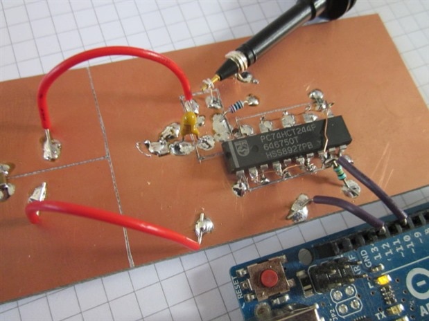
I built my test circuit on a small scrap piece of pcb material using a craft knife to cut the very simple layout
pattern. Here's the circuit diagram and a couple of photographs of the completed test board. It's not very clear from
the photographs but, whilst most of the IC pins are soldered down to copper, the buffer inputs are all bent up in the
air and have a thin wire connecting them all together and to a 100k pull-down resistor (to keep the outputs low in the
event I don't have the Arduino connected).


The operation is quite straightforward. I wanted to show up the effect of the switching on the supply rail, so I've
paralled the eight buffers in an old 74HCT244 part and have them all driving a low value resistor. When the outputs go
high they direct current from the supply rail to the output load. In theory I'm exceeding the datasheet value for the
drive current for each buffer but I'm sure they'll manage - I'm going to have a short pulse of ten microseconds, on a
long duty cycle, so the buffer dissipation won't be very high. I'll then look at the drop of voltage on the rail as the
capacitors initially fail to hold it. By varying the capacitors, I can look at the effects of different sorts of parts,
both individually and in combination. I'm going to do that by actually soldering the parts to the board - any kind of
socket arrangement might affect the results too much.
For a pulse generator I'm going to use my trusty Arduino Uno. The signal from an output pin is fast and fairly clean and
will drive the buffers nicely. You can see from the circuit that I was going to series terminate it but, in the end, I
just kept the leads short and didn't bother.
The inductors you see on the circuit aren't actual coils. Instead, the small amount of inductance comes from the red
pieces of wire looped up above the board's surface. They are there to model the inductance that would come from having
thin power tracks on a board. Doing it like this saves me the effort of carving tracks into the pcb board copper. Each
lead is about 2 inches (5cm) long.
This is, of course, all much worse than you would normally see on a pcb, particularly if fat tracks or, even better,
power planes (the fattest of tracks!) were used, but the point of it all is not to show good practice but to exaggerate
the effects so that we can, hopefully, see some comparative differences between various combinations of capacitors.
The Results
These were the initial oscilloscope traces. The blue trace is the input signal from the Uno. The yellow trace is the
power Vcc at the chip (relative to the chip ground) and has a 5V offset on it, so the marker is at 5V and we are looking
at how it dips down from there when the buffer outputs start driving the load resistor. Using the offset like this lets
me look in more detail at that change without the uncertainty that there would be if I AC-coupled it. This trace is with
no decoupling, so it should be the worst-case one (it was).

The rail dips by about 1.5V before the inductance sorts itself out and allows the increased current to flow from the
group of input capacitors.
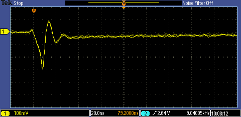
The next one is with a 10uF electrolytic (brand name is 'Forever', which is probably a touch optimistic for a cheap
electrolytic). This one did much better than I expected. [Note that the vertical scale has changed and is now 100mV per
division, rather than the 500mV per division I had before.]
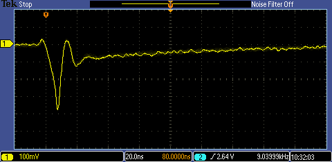
Next up is a 100nF multi-layer ceramic capacitor by itself. All these parts are conventional with leads, so there will
be more lead inductance than there would be with a SMT device.
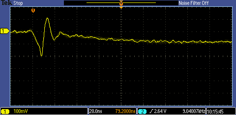
This can supply current faster than the electrolytic. Notice that the slight lift of the rail, just before the dip, is
now no longer there. That's probably where the very fast edge of the input signal couples through the various intrinsic
capacitances of the MOSFETs inside the buffers and emerges to momentarily throw the rail up - the ceramic gets off to a
fast enough start to hold the rail fast and stop it moving.
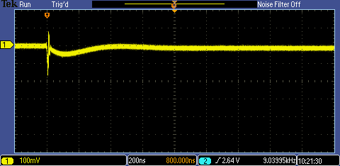
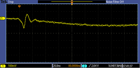
There is a snag, though. Look at the way the trace then sags rather than charge back to the 5V. If we look at that on a
longer timescale, we see this:

The much lower ESR of the ceramic part gives little damping so, as a result of the shock from the sudden switching of
the buffers, energy courses back and forth between the electric field in the capacitor and the magnetic field
established around each of the pair of leads.
Next I've got the previous two devices in parallel, so we have both the electrolytic and ceramic in circuit

Not surprisingly, this looks like a merging together of the results for the two individual components. They hold up
together better than either did by itself. There is still a dip to the subsequent recharging but, looked at on a longer
timescale again, it can be seen that it comes under control much quicker than before because energy is also flowing in
and out of the electrolytic and with a fairly high ESR it dissipates the energy fairly quickly.
Next, I thought I'd try a 3.3uF tantalum bead capacitor by itself. I imagined it would do better than the electrolytic
but, to my surprise, it didn't.
All the components so far have been conventional parts. This next one is an 0805 100nF MLCC.
That gives the best hold-up immediately after the trigger point on the trace so far. But, like its leaded counterpart,
it rings very badly

Conclusions
I'm going to leave it there for the moment. The whole thing wasn't very scientific or comprehensive, and the methodology
was just a bit iffy, but hopefully it was of interest and gives a few pointers to some of the physics that's going on
and the things you might consider. The inspiration for it came from the application note [1] below, though I adapted it
to work with a buffer chip rather than a transistor.
Well, that's what I first wrote but, thinking on it further, I've decided that it is actually quite a poor experiment,
in spite of it looking quite good written up as a blog. Having the output of the buffers driving a load is all a bit
irrelevant - by the time the buffers are doing that (HCT isn't the fastest logic ever) the magnetic fields around the
wires have completed their changes and the current is largely being supplied again from the input capacitors. The
telling moment is when the buffers are first switching and the difference between the MLCCs, one with conventional leads
and the other SMT, suggests that it might be the capacitor lead inductance that is the real key to this. I think I need
a better appreciation of the currents that are flowing at that moment in time to tease this apart.
As usual, any thoughts, ideas, or criticisms are welcome. Feel free to give me a lecture and tell me how I should be
doing this [but please don't tell me I should go out and buy a top-of-the-range VNA because I can't afford it].
Footnote
I realised afterwards, when I was looking at the photographs in Gimp, just how old that HCT244 part is. It's got the old
Philips logo on it and the date code says 89 (ie 1989). Thirty years old!
If you found this interesting and would like to see more blogs I've written, a list can be found here: jc2048 Blog Index
Notes
[1] Linear Technology Application Note 40. Richard Markell. See Appendix B, starting on page 26.
https://www.analog.com/media/en/technical-documentation/application-notes/an40f.pdf
Top Comments
-

DAB
-
Cancel
-
Vote Up
+5
Vote Down
-
-
Sign in to reply
-
More
-
Cancel
-

jc2048
in reply to DAB
-
Cancel
-
Vote Up
+1
Vote Down
-
-
Sign in to reply
-
More
-
Cancel
Comment-

jc2048
in reply to DAB
-
Cancel
-
Vote Up
+1
Vote Down
-
-
Sign in to reply
-
More
-
Cancel
Children