


1. Strategic Component Selection in Modern and Legacy Systems
In high-precision circuit design and the restoration of legacy hardware, passive component selection is a key determinant of system reliability — thermal stability and electrical “quietness” under operation directly affect signal integrity and Mean Time Between Failures (MTBF). This guide summarizes bench-test data across multi-turn trimmers, film capacitors, and electrolytic capacitors, and translates common lab metrics — leakage current, ESR, resistance variance — into practical selection and repair decisions.
2. High-Precision Tuning: Multi-Turn Trimmer Application
Multi-turn trimmers are essential for precision calibration in feedback loops and voltage reference circuits. In these sensitive applications, electrical “quietness” — the absence of noise or “scratchiness” during the wiper’s travel — is the primary quality metric. A noisy interface can introduce erratic voltage spikes, destabilizing the circuit during the calibration phase.
Mechanical Configurations and Footprints
Multi-turn trimmers are commonly available in several physical configurations to accommodate specific mounting requirements and accessibility constraints:
|
Footprint Type |
Adjustment Orientation |
Ideal Application |
|
Inline pins |
Top adjustment |
Standard breadboarding or low-density PCB layouts |
|
Inline pins |
Side adjustment |
High-density vertical mounting; slotting cards with edge access |
|
Horizontal body |
Side adjustment |
Low-profile requirements where vertical height is strictly restricted |
|
Offset legs |
Top adjustment |
Applications requiring increased mechanical stability on the PCB |
|
Offset legs |
Side adjustment |
Vertical mounting with side-access for chassis-enclosed calibration |
Performance Analysis and Stability
Bench-test evaluations of 10kΩ-rated parts reveal critical data points for the hardware consultant. As with any batch of general-purpose trimmers, individual units land at different points within the rated tolerance — this is normal and expected, not a sign of inconsistent manufacturing:
- Resistance variance: Across a 5-unit batch (inline pins, top adjustment), measured values ranged 9.2–10.1kΩ on a 10kΩ part — within the ±10–20% tolerance typical of this part class, not evidence of a manufacturing bias. (A separate spot-check on a different footprint measured 10.2kΩ; see the appendix for the full breakdown.) Design the tuning range to cover the full rated tolerance window rather than assuming a centered value.
- NTC / thermal drift: An observed resistance drift downward was seen with warming during handling — finger contact during adjustment transfers heat, and this is consistent with the negative temperature coefficient typical of this part class, though the handling test wasn’t a controlled-temperature measurement. Use an insulated trimming tool and allow a brief cooling period before finalizing a calibration.
- Wiper integrity: Clean, glitch-free travel across the full 25-turn range in all samples tested — no erratic jumps that would destabilize an active feedback loop.
3. Power Integrity and Safety: X/Y Class and Film Capacitors
Power input stages demand capacitors capable of withstanding high-voltage transients while providing effective EMI/RFI filtering.
Metallized Polypropylene Film Capacitors
These components are characterized by exceptional dielectric integrity.
- Voltage ceiling performance: Commonly available in 250V, 630V, and 1000V ratings, with no measurable leakage recorded at full rated voltage. A separate test also pushed a 250V-rated part to 1000V DC (4x rated voltage) purely as a destructive bench overvoltage test — this is not a working condition and should not be read as one. It’s a lab exercise to find the absolute breakdown limit, and it also showed no measurable leakage, but that result carries no implication for normal use. In actual circuit design, operating voltage must stay within the part’s rated voltage with standard derating applied (roughly ≤80% of rated voltage for continuous duty) — the rated voltage is the working limit, full stop.
- Observed accuracy: Measured values frequently beat spec — a 0.047µF part measured 0.0467µF, tighter than the standard ±5% tolerance.
Safety Capacitor Repair Strategy
A primary maintenance task is the replacement of aged epoxy-cased safety capacitors (such as the classic “Rifa” style) in legacy equipment (20–30+ years old).
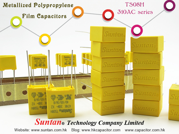
- Legacy replacement: Failing legacy safety caps are prone to thermal runaway and casing rupture, releasing corrosive smoke. Modern X2-rated capacitors (310V AC) are a reliable replacement for mains filtering — a tested 0.1µF/310V sample measured 0.104µF with no measurable leakage at 350V DC.
- Y-Class selection (line-to-ground): For Y-Class parts (400V), prioritize voltage rating and safety certification over capacitance tolerance — ±20% is acceptable for line-to-ground filtering, but low leakage is non-negotiable. A 4.7nF/400V sample measured 4.8nF with no measurable leakage at full rated voltage.
4. Legacy Maintenance: Axial Electrolytic Capacitor Replacement Logic
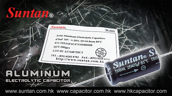
Axial electrolytic capacitors are increasingly scarce in a market dominated by radial and SMD formats. For the restoration of vintage audio and industrial gear, identifying reliable modern axial alternatives is essential for preserving original circuit topology and performance.
Thermal Rating and Longevity
Higher-grade axial capacitors rated for 105°C represent a significant upgrade over the 85°C parts standard in legacy designs.
- MTBF impact: In poorly ventilated enclosures, this higher thermal ceiling dramatically increases the Mean Time Between Failures.
- ESR benchmark: High-quality health is evidenced by low equivalent series resistance. A tested 470µF/40V unit (measuring 480µF) showed an ESR of 0.02Ω, confirming excellent performance for power supply filtering.
Technical Caution: Reforming and Dielectric Absorption
Electrolytic capacitors are chemical devices subject to aging while in storage — this is a universal characteristic of aluminum electrolytic technology across every manufacturer, not a defect specific to any one product line. As a general storage guideline, electrolytic capacitors are best used within about 2 years of purchase; beyond that window, dielectric aging becomes more pronounced and reforming before installation becomes more important, so stock rotation (first-in, first-out) is worth building into inventory practice for any shelf that holds these parts.
- The reforming process: Long-stored capacitors (6+ months) may show high initial leakage (e.g., 200µA), settling to ~30µA within minutes once energized at rated voltage as the aluminum oxide dielectric rebuilds. This is expected, well-documented behavior for any electrolytic capacitor that’s sat on a shelf for an extended period, and reforming before installation is standard industry practice, not a sign of a defective part. Leakage convergence, alongside ESR returning to normal, is the primary indicator that reforming succeeded — Dielectric Absorption (DA) is sometimes cited too, but it’s a property of the dielectric material itself (healthy aluminum oxide typically reads 8–15% anyway) and can be misread on some analyzers when leakage is still high, so treat a falling DA reading as supporting evidence at most, not the pass/fail criterion.
5. Final Engineering Recommendations and Comparative Summary
Component Application Matrix
|
Component Category |
Key Differentiator |
Ideal Application |
Maintenance/Design Tip |
|
Multi-turn trimmers |
25-turn, noise-free travel |
Precision calibration / feedback |
Measured variance (9.2–10.1kΩ on a 10kΩ part, 5-unit lot) fell within normal trimmer tolerance; design the tuning range to cover the full tolerance window rather than assuming a centered value |
|
Film capacitors |
No measurable leakage at rated voltage |
High-voltage DC coupling |
Tolerances often exceed spec (e.g., 0.0467µF for a 0.047µF part); overvoltage bench testing is for characterization only, not a working condition — follow standard derating in actual designs |
|
X2/Y safety capacitors |
Safety-rated (310V/400V) |
Mains EMI/RFI filtering |
Essential replacement for aged epoxy-cased caps to prevent corrosive smoke |
|
Axial electrolytics |
105°C rating; 0.02Ω ESR |
Vintage audio/industrial gear |
Reform if stored >6 months; judge success by leakage current and ESR normalizing, not by DA alone |
Takeaways
- Reliability-to-cost ratio: Well-specified components in these categories offer high dielectric integrity and safety ratings, making them cost-effective for both new designs and high-stakes professional maintenance.
- Mechanical versatility: The range of trimmer footprints and the availability of 105°C-rated axial caps solve real integration and scarcity issues in the repair industry.
- Superior thermal profile: The transition to 105°C ratings for electrolytic components is a meaningful advantage for equipment longevity in high-heat or legacy enclosures.
- Storage matters: Electrolytic capacitors perform best when used within roughly 2 years of purchase. Longer storage doesn’t necessarily make a part unusable, but it does mean reforming before installation, and inventory practices that favor stock rotation, become more important.
Bench data above reflects a limited sample set; results may vary by manufacturer and batch. Feedback and comparative measurements from others working on similar restorations are welcome.
Appendix: Trimmer Batch — Individual Sample Data
The resistance-variance summary in Section 2 is drawn from this batch. The first five rows are one 5-unit lot of the same footprint (inline pins, top adjustment); the remaining rows are single spot-checks of other mechanical variants, not part of that lot. All values fall within normal trimmer tolerance — see Section 2 for context.
|
Footprint |
Measured Resistance (10kΩ nominal) |
|
Inline pins, top adjustment — Sample 1 |
9.5 kΩ |
|
Inline pins, top adjustment — Sample 2 |
9.2 kΩ |
|
Inline pins, top adjustment — Sample 3 |
10.0 kΩ |
|
Inline pins, top adjustment — Sample 4 |
10.1 kΩ |
|
Inline pins, top adjustment — Sample 5 |
9.6 kΩ |
|
Inline pins, side adjustment |
9.3 kΩ |
|
Offset legs, top adjustment |
10.2 kΩ |
|
Offset legs, side adjustment |
9.5 kΩ |
|
Horizontal body, side adjustment |
10.2 kΩ |
Small sample set for illustration, not a statistically representative qualification report.