element14 Community
element14 Community
    Register Log In
  • Site
  • Search
  • Log In Register
  • Community Hub
    Community Hub
    • What's New on element14
    • Feedback and Support
    • Benefits of Membership
    • Personal Blogs
    • Members Area
    • Achievement Levels
  • Learn
    Learn
    • Ask an Expert
    • eBooks
    • element14 presents
    • Learning Center
    • Tech Spotlight
    • STEM Academy
    • Webinars, Training and Events
    • Learning Groups
  • Technologies
    Technologies
    • 3D Printing
    • FPGA
    • Industrial Automation
    • Internet of Things
    • Power & Energy
    • Sensors
    • Technology Groups
  • Challenges & Projects
    Challenges & Projects
    • Design Challenges
    • element14 presents Projects
    • Project14
    • Arduino Projects
    • Raspberry Pi Projects
    • Project Groups
  • Products
    Products
    • Arduino
    • Avnet Boards Community
    • Dev Tools
    • Manufacturers
    • Multicomp Pro
    • Product Groups
    • Raspberry Pi
    • RoadTests & Reviews
  • Store
    Store
    • Visit Your Store
    • Choose another store...
      • Europe
      •  Austria (German)
      •  Belgium (Dutch, French)
      •  Bulgaria (Bulgarian)
      •  Czech Republic (Czech)
      •  Denmark (Danish)
      •  Estonia (Estonian)
      •  Finland (Finnish)
      •  France (French)
      •  Germany (German)
      •  Hungary (Hungarian)
      •  Ireland
      •  Israel
      •  Italy (Italian)
      •  Latvia (Latvian)
      •  
      •  Lithuania (Lithuanian)
      •  Netherlands (Dutch)
      •  Norway (Norwegian)
      •  Poland (Polish)
      •  Portugal (Portuguese)
      •  Romania (Romanian)
      •  Russia (Russian)
      •  Slovakia (Slovak)
      •  Slovenia (Slovenian)
      •  Spain (Spanish)
      •  Sweden (Swedish)
      •  Switzerland(German, French)
      •  Turkey (Turkish)
      •  United Kingdom
      • Asia Pacific
      •  Australia
      •  China
      •  Hong Kong
      •  India
      •  Korea (Korean)
      •  Malaysia
      •  New Zealand
      •  Philippines
      •  Singapore
      •  Taiwan
      •  Thailand (Thai)
      • Americas
      •  Brazil (Portuguese)
      •  Canada
      •  Mexico (Spanish)
      •  United States
      Can't find the country/region you're looking for? Visit our export site or find a local distributor.
  • Translate
  • Profile
  • Settings
Passive Components
  • Technologies
  • More
Passive Components
Forum Why are the Triac Snubber Resistors Failing in this circuit.
  • Blog
  • Forum
  • Documents
  • Quiz
  • Events
  • Polls
  • Members
  • Mentions
  • Sub-Groups
  • Tags
  • More
  • Cancel
  • New
Join Passive Components to participate - click to join for free!
Actions
  • Share
  • More
  • Cancel
Forum Thread Details
  • State Verified Answer
  • Replies 15 replies
  • Answers 6 answers
  • Subscribers 109 subscribers
  • Views 6543 views
  • Users 0 members are here
  • triac_snubber_circuit
Related

Why are the Triac Snubber Resistors Failing in this circuit.

jw0752
jw0752 over 5 years ago

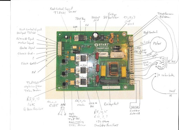
I have recently been repairing power supply / control circuit boards for a small machine that cuts tape to a specified length. Here is a picture of the circuit board in question along with my notes so far:


image


Here is the schematic that I have reverse engineered from the circuit board:


image


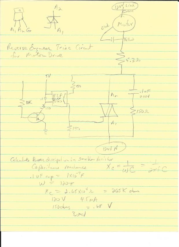
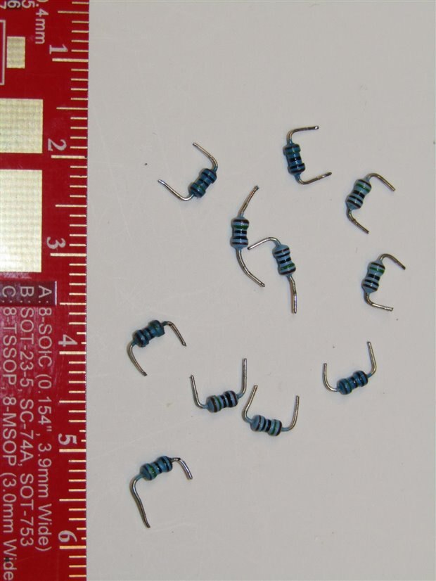
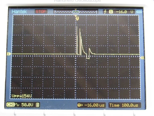
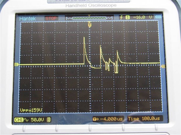
I have been working my way through a box of circuit boards, that were replaced in the past as black boxes, and repairing them. I have noticed that on almost every board the 150 Ohm 1/8 Watt snubber resistors are open or showing meg ohms of resistance. I have done the math for the circuit and with our local 120 volt 60 Hz line voltage the .1 uF cap in series with the 150 Ohm resistor should have 4.5 mA of current and a corresponding 3 mW of power delivered to the resistor. Since the resistor appears to be an eighth Watt there should be plenty of room for it to handle this voltage, current and wattage.


Unfortunately I am finding almost 100% of these 150 Ohm snubber resistors failed. There are more of the same 150 Ohm 1/8 Watt resistors used on this board in other parts of the circuit but the only ones that are failing are in the snubber circuit.


I am hoping that someone with more experience than me can tell me what is going on in this circuit that is taking out the snubber resistors. The Triacs drive a Variable direction motor and a large solenoid so the loads are definitely inductive. The little resistors do not look heat damaged. They also do not look to be of high quality if that may be a contributing factor.


Any insights you may have will be appreciated.


John

  • Sign in to reply
  • Cancel

Top Replies

  • dougw
    dougw over 5 years ago +7 verified
    I am not an expert in this but here is my speculation: Typical 1/8th watt metal film resistors may be rated for 200-250 V and your inductive spike might be higher. Typically these resistors are internally…
  • jw0752
    jw0752 over 5 years ago in reply to fmilburn +7 suggested
    The calculations show that under the line voltage (120) with no spikes the resistor itself has only 0.6 volts rms across it. This however hides the reality of the large swings in voltage as the capacitor…
  • jw0752
    jw0752 over 5 years ago +7 suggested
    Tonight I set up a circuit using the motor and snubber circuit from the machine I am working on. Instead of a Triac I am using a mechanical snap action switch to turn the motor on and off. Here is a picture…
  • dougw
    0 dougw over 5 years ago

    I am not an expert in this but here is my speculation:

    Typical 1/8th watt metal film resistors may be rated for 200-250 V and your inductive spike might be higher.

    Typically these resistors are internally "spiral cut" (to automate trimming to specific values) and a high voltage spike can cause flash-over between the cuts.

    This could evaporate the material locally causing an open circuit without burning the whole resistor.

    • Cancel
    • Vote Up +7 Vote Down
    • Sign in to reply
    • Verify Answer
    • Reject Answer
    • Cancel
  • jw0752
    0 jw0752 over 5 years ago in reply to dougw

    Hi Doug,


    That makes good sense. Here is a picture of some of the little failed beasties. The next time I have a test jig set up I will try to see what the spike looks like with my scope.


    image


    John

    • Cancel
    • Vote Up +4 Vote Down
    • Sign in to reply
    • Verify Answer
    • Cancel
  • fmilburn
    0 fmilburn over 5 years ago in reply to dougw

    I don't work with mains voltage and learned something :-)  A quick look shows that it is possible to get a 500 V, 2 Watt metal film resistor for less than 4 cents.  How would one calculate or estimate the required voltage rating?

    • Cancel
    • Vote Up +5 Vote Down
    • Sign in to reply
    • Verify Answer
    • Reject Answer
    • Cancel
  • fmilburn
    0 fmilburn over 5 years ago in reply to fmilburn

    I suppose one could hook up their oscilloscope as John suggests and see :-)

    • Cancel
    • Vote Up +5 Vote Down
    • Sign in to reply
    • Verify Answer
    • Cancel
  • jw0752
    0 jw0752 over 5 years ago in reply to fmilburn

    The calculations show that under the line voltage (120) with no spikes the resistor itself has only 0.6 volts rms across it. This however hides the reality of the large swings in voltage as the capacitor charges and discharges. Doug's speculation seems to be a good one to me. I am going to set up an experiment and look at the situation with the scope tonight.


    John

    • Cancel
    • Vote Up +7 Vote Down
    • Sign in to reply
    • Verify Answer
    • Reject Answer
    • Cancel
  • fmilburn
    0 fmilburn over 5 years ago in reply to jw0752

    Yes, I agree.  I was wondering if there was a rule of thumb or way to guesstimate the voltage rating needed to handle the spikes.  I did a quick search last night and did not see anything.

    • Cancel
    • Vote Up +5 Vote Down
    • Sign in to reply
    • Verify Answer
    • Cancel
  • three-phase
    0 three-phase over 5 years ago in reply to fmilburn

    If you have a lot of familiarity with snubber circuits and the load, then you may be able to make an educated guess. There are calculations available to work out what the peak back emf will be, but they require know about the inductance and physical characteristics of the motor and its winding. How fast the semiconductor is switched off also affects the voltage seen.


    Remember that the calculations made are based upon rms, which will not be the peak voltage of an AC supply.


    If you are really up for the theory and the maths, then there is this paper from ABB on snubber design, more into thyristors but the principles will be the same. Then again, as admitted within the paper, the easiest and usually most accurate is to measure it.


    ABB Snubber Circuit Design


    Kind regards

    • Cancel
    • Vote Up +6 Vote Down
    • Sign in to reply
    • Verify Answer
    • Reject Answer
    • Cancel
  • fmilburn
    0 fmilburn over 5 years ago in reply to three-phase

    Thanks Donald,


    this pretty much confirms why I should not be designing high voltage stuff

    • Cancel
    • Vote Up +6 Vote Down
    • Sign in to reply
    • Verify Answer
    • Cancel
  • neilk
    0 neilk over 5 years ago in reply to fmilburn

    Me neither!! I get sweaty palms above 12V!!


    Neil

    • Cancel
    • Vote Up +6 Vote Down
    • Sign in to reply
    • Verify Answer
    • Cancel
  • jw0752
    0 jw0752 over 5 years ago

    Tonight I set up a circuit using the motor and snubber circuit from the machine I am working on. Instead of a Triac I am using a mechanical snap action switch to turn the motor on and off. Here is a picture of the setup.


    image

    The motor has two windings with a 6 uF capacitor between them. 120 volts is hooked up across one of the windings and the second winding gets the out of phase voltage through the capacitor. This causes the motor to rotate in one direction. If the other winding of the motor is hooked up across the 120 volts the motor will rotate in the opposite direction. For my first test I did not hook up the motor capacitor. I put the voltage across one winding and looked at the spike that was generated. This should give the worst case spike, much the same as if the motor was under a heavy load. Here is what I found:


    imageimage

    As you can see there is a 337 volt PP spike with a max voltage of 179 volts across the 150 Ohm resistor.


    I next hooked up the capacitor so that the motor would rotate. Here are the most severe spikes from a series of tests starts.


    imageimage


    We are still seeing a max voltage spike of between 150 and 160 volts into the 150 ohm resistor.


    I can see now that the voltages could have very easily exceeded specifications on the little resistors that were used on these boards. This would further support Doug's hypothesis.


    John

    • Cancel
    • Vote Up +7 Vote Down
    • Sign in to reply
    • Verify Answer
    • Reject Answer
    • Cancel
>
element14 Community

element14 is the first online community specifically for engineers. Connect with your peers and get expert answers to your questions.

  • Members
  • Learn
  • Technologies
  • Challenges & Projects
  • Products
  • Store
  • About Us
  • Feedback & Support
  • FAQs
  • Terms of Use
  • Privacy Policy
  • Legal and Copyright Notices
  • Sitemap
  • Cookies

An Avnet Company © 2025 Premier Farnell Limited. All Rights Reserved.

Premier Farnell Ltd, registered in England and Wales (no 00876412), registered office: Farnell House, Forge Lane, Leeds LS12 2NE.

ICP 备案号 10220084.

Follow element14

  • X
  • Facebook
  • linkedin
  • YouTube