element14 Community
element14 Community
    Register Log In
  • Site
  • Search
  • Log In Register
  • About Us
  • Community Hub
    Community Hub
    • What's New on element14
    • Feedback and Support
    • Benefits of Membership
    • Personal Blogs
    • Members Area
    • Achievement Levels
  • Learn
    Learn
    • Ask an Expert
    • eBooks
    • element14 presents
    • Learning Center
    • Tech Spotlight
    • STEM Academy
    • Webinars, Training and Events
    • Learning Groups
  • Technologies
    Technologies
    • 3D Printing
    • FPGA
    • Industrial Automation
    • Internet of Things
    • Power & Energy
    • Sensors
    • Technology Groups
  • Challenges & Projects
    Challenges & Projects
    • Design Challenges
    • element14 presents Projects
    • Project14
    • Arduino Projects
    • Raspberry Pi Projects
    • Project Groups
  • Products
    Products
    • Arduino
    • Avnet Boards Community
    • Dev Tools
    • Manufacturers
    • Multicomp Pro
    • Product Groups
    • Raspberry Pi
    • RoadTests & Reviews
  • Store
    Store
    • Visit Your Store
    • Choose another store...
      • Europe
      •  Austria (German)
      •  Belgium (Dutch, French)
      •  Bulgaria (Bulgarian)
      •  Czech Republic (Czech)
      •  Denmark (Danish)
      •  Estonia (Estonian)
      •  Finland (Finnish)
      •  France (French)
      •  Germany (German)
      •  Hungary (Hungarian)
      •  Ireland
      •  Israel
      •  Italy (Italian)
      •  Latvia (Latvian)
      •  
      •  Lithuania (Lithuanian)
      •  Netherlands (Dutch)
      •  Norway (Norwegian)
      •  Poland (Polish)
      •  Portugal (Portuguese)
      •  Romania (Romanian)
      •  Russia (Russian)
      •  Slovakia (Slovak)
      •  Slovenia (Slovenian)
      •  Spain (Spanish)
      •  Sweden (Swedish)
      •  Switzerland(German, French)
      •  Turkey (Turkish)
      •  United Kingdom
      • Asia Pacific
      •  Australia
      •  China
      •  Hong Kong
      •  India
      •  Korea (Korean)
      •  Malaysia
      •  New Zealand
      •  Philippines
      •  Singapore
      •  Taiwan
      •  Thailand (Thai)
      • Americas
      •  Brazil (Portuguese)
      •  Canada
      •  Mexico (Spanish)
      •  United States
      Can't find the country/region you're looking for? Visit our export site or find a local distributor.
  • Translate
  • Profile
  • Settings
Passive Components
  • Technologies
  • More
Passive Components
Forum Fluid Control Solenoid Unusual Readings
  • Blog
  • Forum
  • Documents
  • Quiz
  • Events
  • Polls
  • Members
  • Mentions
  • Sub-Groups
  • Tags
  • More
  • Cancel
  • New
Join Passive Components to participate - click to join for free!
Actions
  • Share
  • More
  • Cancel
Forum Thread Details
  • State Verified Answer
  • Replies 7 replies
  • Answers 3 answers
  • Subscribers 108 subscribers
  • Views 2852 views
  • Users 0 members are here
  • solenoid_coil
Related

Fluid Control Solenoid Unusual Readings

jw0752
jw0752 over 4 years ago

image


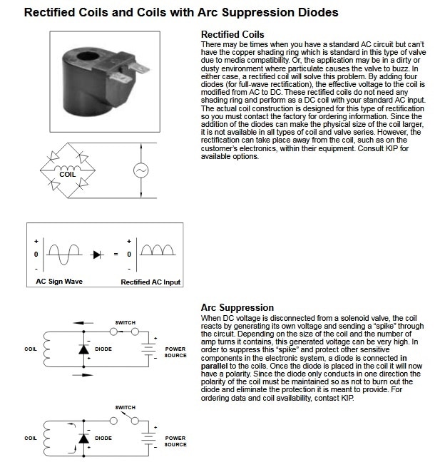
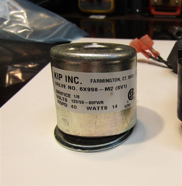
This is the coil from a solenoid that is used in a dental counter top sterilizer. When it is energized it pulls a plunger away from a valve seat and lets water flow through the valve and into the sterilization chamber. While I was working on a sterilizer a while back I got some really strange readings on my ohmmeter when I attempted to verify continuity in the coil of this solenoid. Further tests on other coils in other sterilizers showed that my unusual readings were consistent with this style solenoid.


As one can see from the label this coil is designed for 120 Volts 50 to 60 Hz and is rated at 14 Watts which would indicate a current draw of approximately 100 mA and a DC resistance of approximately 1K Ohms.

The Ohms reading I was getting however from various digital meters was more in the area of 500K Ohms. I hooked the coil up on the bench and applied 115 Volts AC to it and got a current reading of about 100 mA as expected.  Still the digital meters all said the resistance was 500K Ohms. When I tried using one of my analog Ohmmeters I got a resistance reading of about 800 Ohms. The coil was acting very much as if there was a semiconductor junction in series with the coil. I had seen this before when I have attempted to read polarity on a diode using the Ohms scale of digital meters. The digital meters do not use a high enough test voltage to overcome the junction energy level and therefore do not give an accurate reading. The analog meter on the other hand uses 3 volts and therefore can read the resistance past the semiconductor.


I continued my tests by reversing the polarity of my test leads and found that there was no noticeable polarity discrimination. I got the same 800 Ohms on the analog meter and 500K on the digital meter regardless of the polarity of the test leads. When I switched the digital meter to Diode Test it told me that the energy barrier that I was dealing with was about 1.9 Volts. This would be close to three Si diodes in series with the coil and since there was no polarity preference there must be an additional 3 Si diodes reverse polarity in parallel with the first three diodes.


Now I have no way of knowing if these are standard diodes or some other semiconductor such as a NTC or PTC Thermistor or some other type of semiconductor. Whatever it is, it is molded into the plastic shell that is formed around the coil itself and not visibly evident.


I attempted to find data sheets on the coil from the manufacturer but there was nothing to indicate that it is anything other than a simple coil.


My question is: Does anyone have any idea of what type of semiconductor might have been put integrally in line with the coil of this solenoid and what purpose would it serve? Does my analysis of this actually being a semiconductor in series with the coil make sense? Are there any other possible explanations?


The solenoid, when in operation, must dissipate the 14 Watts that is generated by it and it is in an already hot 80 degree C environment. The fluids flowing through it are as hot as 100 C. Other than being in a hot environment and handling hot fluids there is nothing really unusual about the solenoid. Also in recent models of this sterilizer a different solenoid is being used that does not have the anomalous readings of the older style solenoid. The new solenoid has a roughly 1K DC resistance that is readable by both the Digital and Analog Ohm meters.


Any insights will be appreciated.


John

  • Sign in to reply
  • Cancel

Top Replies

  • genebren
    genebren over 4 years ago +5 verified
    John, I could not find any specifications that match that part number. I did however find some KIP catalogs that described other valves and had some text regarding coil selections in their product lines…
  • jw0752
    jw0752 over 4 years ago in reply to genebren +5 suggested
    Hi Gene, Thank you for your insight. The coil definitely had an internal bridge. I hooked it up to 100V DC and observed the polarity of the magnetic field. When I reversed the polarity of the 100 VDC the…
  • fmilburn
    fmilburn over 4 years ago +3 suggested
    Hi John, I don’t know the answers (of course) but what happens if you put your DC power supply across it and slowly bump the voltage up while measuring current so as to plot an IV curve? Nice mystery to…
  • genebren
    0 genebren over 4 years ago

    John,


    I could not find any specifications that match that part number.  I did however find some KIP catalogs that described other valves and had some text regarding coil selections in their product lines.  There were two coil types that had diodes inside the coil housing.

    image

    I could see where the Arc suppression type could might give you a different reading based on the VOM lead placement (high impedance in one direction, low in the other).  The Rectified coil might give you high impedance reading if the voltage applied is not enough to forward bias the two diodes in series with the coil.


    Good luck!

    Gene

    • Cancel
    • Vote Up +5 Vote Down
    • Sign in to reply
    • Verify Answer
    • Reject Answer
    • Cancel
  • fmilburn
    0 fmilburn over 4 years ago

    Hi John,

    I don’t know the answers (of course) but what happens if you put your DC power supply across it and slowly bump the voltage up while measuring current so as to plot an IV curve?  Nice mystery to ponder for a snowy day here in Portland.
    Frank

    • Cancel
    • Vote Up +3 Vote Down
    • Sign in to reply
    • Verify Answer
    • Reject Answer
    • Cancel
  • DAB
    0 DAB over 4 years ago

    Hi John,


    You are probably dealing with two issues.

    First, the ohm meter uses DC voltage and when you put it across the coil, you will get a very high ohm reading as the coil has to build a magnetic field, which could take some time depending upon the LR time constant.

    Second, the solenoid probably uses a diode to make it safe from EMF reverse current when the magnetic field collapses. You have seen many motor designs with diodes across the coils for the same reason. This is just a way to protect other devices from a potentially high voltage spike.


    Good job of deductive reasoning.


    DAB

    • Cancel
    • Vote Up +3 Vote Down
    • Sign in to reply
    • Verify Answer
    • Reject Answer
    • Cancel
  • fmilburn
    0 fmilburn over 4 years ago in reply to genebren

    Nice find!

    • Cancel
    • Vote Up +3 Vote Down
    • Sign in to reply
    • Verify Answer
    • Cancel
  • jw0752
    0 jw0752 over 4 years ago in reply to genebren

    Hi Gene,


    This may be the answer. I should be able to check it by looking at the resultant magnetic field of the coil when a voltage is applied. If there is a bridge between the input and the coil it will have the same N-S orientation regardless of the polarity of the DC voltage that I apply to it. I am heading for the shop right now to perform this experiment. It also makes sense as the newer replacement coil that is currently being used in the sterilizer come with an external bridge circuit that is plugged in between the control board and the solenoid.


    John

    • Cancel
    • Vote Up +2 Vote Down
    • Sign in to reply
    • Verify Answer
    • Cancel
  • jw0752
    0 jw0752 over 4 years ago in reply to fmilburn

    Hi Frank,


    This is a great suggestion. I am going to run an experiment based on Gene's suggestion and if that doesn't solve the problem I am going to map the current as you suggested.


    John

    • Cancel
    • Vote Up +2 Vote Down
    • Sign in to reply
    • Verify Answer
    • Cancel
  • jw0752
    0 jw0752 over 4 years ago in reply to genebren

    Hi Gene,


    Thank you for your insight. The coil definitely had an internal bridge. I hooked it up to 100V DC and observed the polarity of the magnetic field. When I reversed the polarity of the 100 VDC the field maintained its previous polarity. Mystery solved.


    John

    • Cancel
    • Vote Up +5 Vote Down
    • Sign in to reply
    • Verify Answer
    • Reject Answer
    • Cancel
element14 Community

element14 is the first online community specifically for engineers. Connect with your peers and get expert answers to your questions.

  • Members
  • Learn
  • Technologies
  • Challenges & Projects
  • Products
  • Store
  • About Us
  • Feedback & Support
  • FAQs
  • Terms of Use
  • Privacy Policy
  • Legal and Copyright Notices
  • Sitemap
  • Cookies

An Avnet Company © 2025 Premier Farnell Limited. All Rights Reserved.

Premier Farnell Ltd, registered in England and Wales (no 00876412), registered office: Farnell House, Forge Lane, Leeds LS12 2NE.

ICP 备案号 10220084.

Follow element14

  • X
  • Facebook
  • linkedin
  • YouTube