element14 Community
element14 Community
    Register Log In
  • Site
  • Search
  • Log In Register
  • Community Hub
    Community Hub
    • What's New on element14
    • Feedback and Support
    • Benefits of Membership
    • Personal Blogs
    • Members Area
    • Achievement Levels
  • Learn
    Learn
    • Ask an Expert
    • eBooks
    • element14 presents
    • Learning Center
    • Tech Spotlight
    • STEM Academy
    • Webinars, Training and Events
    • Learning Groups
  • Technologies
    Technologies
    • 3D Printing
    • FPGA
    • Industrial Automation
    • Internet of Things
    • Power & Energy
    • Sensors
    • Technology Groups
  • Challenges & Projects
    Challenges & Projects
    • Design Challenges
    • element14 presents Projects
    • Project14
    • Arduino Projects
    • Raspberry Pi Projects
    • Project Groups
  • Products
    Products
    • Arduino
    • Avnet Boards Community
    • Dev Tools
    • Manufacturers
    • Multicomp Pro
    • Product Groups
    • Raspberry Pi
    • RoadTests & Reviews
  • Store
    Store
    • Visit Your Store
    • Choose another store...
      • Europe
      •  Austria (German)
      •  Belgium (Dutch, French)
      •  Bulgaria (Bulgarian)
      •  Czech Republic (Czech)
      •  Denmark (Danish)
      •  Estonia (Estonian)
      •  Finland (Finnish)
      •  France (French)
      •  Germany (German)
      •  Hungary (Hungarian)
      •  Ireland
      •  Israel
      •  Italy (Italian)
      •  Latvia (Latvian)
      •  
      •  Lithuania (Lithuanian)
      •  Netherlands (Dutch)
      •  Norway (Norwegian)
      •  Poland (Polish)
      •  Portugal (Portuguese)
      •  Romania (Romanian)
      •  Russia (Russian)
      •  Slovakia (Slovak)
      •  Slovenia (Slovenian)
      •  Spain (Spanish)
      •  Sweden (Swedish)
      •  Switzerland(German, French)
      •  Turkey (Turkish)
      •  United Kingdom
      • Asia Pacific
      •  Australia
      •  China
      •  Hong Kong
      •  India
      •  Korea (Korean)
      •  Malaysia
      •  New Zealand
      •  Philippines
      •  Singapore
      •  Taiwan
      •  Thailand (Thai)
      • Americas
      •  Brazil (Portuguese)
      •  Canada
      •  Mexico (Spanish)
      •  United States
      Can't find the country/region you're looking for? Visit our export site or find a local distributor.
  • Translate
  • Profile
  • Settings
Passive Components
  • Technologies
  • More
Passive Components
Forum How Do I Replace a 5 Pin Volume Control (Potentiometer/Variable Resistor)?
  • Blog
  • Forum
  • Documents
  • Quiz
  • Events
  • Polls
  • Members
  • Mentions
  • Sub-Groups
  • Tags
  • More
  • Cancel
  • New
Join Passive Components to participate - click to join for free!
Actions
  • Share
  • More
  • Cancel
Forum Thread Details
  • State Verified Answer
  • Replies 17 replies
  • Answers 4 answers
  • Subscribers 111 subscribers
  • Views 16771 views
  • Users 0 members are here
  • potentiometer
  • variable_resistor
  • 2.1
  • pot
  • mms_110
  • creative
  • Speakers
Related

How Do I Replace a 5 Pin Volume Control (Potentiometer/Variable Resistor)?

Former Member
Former Member over 13 years ago

Hi, this is my first post so please forgive me if this is in the wrong place entirely.

I am currently working on a control panel for my audio and video devices about my room. I have two video inputs, one output. Three Audio inputs, two outputs.
Here is a quick diagram of what I am going for.
image

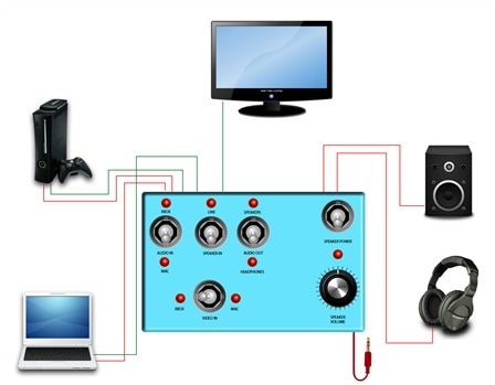
Please note that the connections are haphazardly placed. They do not represent what switches they are intended to work with.
Also, looking again at this picture, the Line Switch switches between having the line or (xbox or mac) Hope that makes sense, however, that is irrelvant to my question.

Red is audio, Green is video. I ahve attached this so you can have the large version if you cannot read the labels.

I have everything figured out except the volume dial for the speakers.

My speakers are Creative SBS 2.1 370. Here is a picture:

http://www.productwiki.com/upload/images/creative_sbs_2_1_370.jpg


So I unscrewed the little controller and I found a switch, 2 resistors, an LED to indicate power on and a 5 pin potentiometer which is the volume control. Also there are 6 cables to the little board.

Now the aim is to replace this board with big parts, a nice big LED, a big toggle switch and a big volume knob. The LED and Switch are very easy to do. I need help with the potentiometer.

I know how a normal 3 pin pot works but I have no idea how to even start

I've been looking everywhere for some kind of wiring diagram but can't find anything.

So this is where I need help. How do I go about replacing this? Is there some method of measuring each pin with an ohmeter? Or are there some datasheets I'm missing?

Here is two photos of the board.
image

image

Circuit is NEPTUNE MMS110 REV A


Sorry to drag this out. Just wanted to make sure I have made myself clear.

The really ghetto way would be to mechanical turn this pot, but I'm curious about how to solve this.
Any advice on how to go about replacing this pot will be greatly appreciated. Please don't hesistate to ask questions or leave comments.

Attachments:
image
  • Sign in to reply
  • Cancel

Top Replies

  • Former Member
    Former Member over 9 years ago in reply to Former Member +2
    yes, it worked for me thank u very much sir.
  • Former Member
    Former Member over 13 years ago +1 verified
    I've figured it out. It's simply a dual gang potentiometer. http://beavishifi.com/articles/Volume_Control/ They seem standard in stereo applications. I had to search quite hard to find this which I find…
  • codename24
    codename24 over 5 years ago +1
    Can anyone explain what is the use of the two resistors on the input L and R?
  • Catwell
    0 Catwell over 13 years ago
    It's probably a 1k rotary pot with single pole switch, and a linear taper. You could also
    use a similar pot with double pole switch (total 7 pins). Both are readily available items.
    You are going to have to get the part number off of it to know for sure.
     
    Let us know.
     
    Cabe
    • Cancel
    • Vote Up 0 Vote Down
    • Sign in to reply
    • Verify Answer
    • Reject Answer
    • Cancel
  • Former Member
    0 Former Member over 13 years ago in reply to Catwell

    Thanks for the response. By single pole switch do you mean that the pot can function as a switch and a potentiometer? I don't think it is one of these because the dial does not click in to any positions. Not aonly that but there is also an on/off slide switch on the board.
    I was hoping I could have the replacement ready before desoldering this thing but maybe one day I'll pluck up the courage and do it.

    I'll post my findings here.

    J

    • Cancel
    • Vote Up 0 Vote Down
    • Sign in to reply
    • Verify Answer
    • Cancel
  • Former Member
    0 Former Member over 13 years ago

    Perhaps this will help. I can't quite get my head around it yet...

    Am I correst in assuming that red and white should both have the same resistance in the potentiometer, because they will need to be at the same volume?

    image

    Oh forgot to add the LED to the green terminal near the bottom of the board.

    • Cancel
    • Vote Up 0 Vote Down
    • Sign in to reply
    • Verify Answer
    • Reject Answer
    • Cancel
  • Former Member
    0 Former Member over 13 years ago

    I've figured it out. image It's simply a dual gang potentiometer. http://beavishifi.com/articles/Volume_Control/ They seem standard in stereo applications. I had to search quite hard to find this which I find quite weird.
    Officially it's 6 pin but the ground is common so it becomes a 5 pin. Now all I have to do is measure the resistance and find a replacement.

    http://beavishifi.com/articles/Volume_Control/Schematic-Volume-Control-Dual-Gang-Potentiometers.gif

    I have desoldered it and it is part number A103 and it's a 10K pot.

    I feel really silly going through all this effort, but hopefully this will someone else with the same question one day. image

    • Cancel
    • Vote Up +1 Vote Down
    • Sign in to reply
    • Verify Answer
    • Reject Answer
    • Cancel
  • Former Member
    0 Former Member over 13 years ago

    Hi,

    I just want to ask if removing the gang pot will automatically set the two speaker channels to full volume..

    I have removed the potentiometer yet only the right channel works.

    • Cancel
    • Vote Up 0 Vote Down
    • Sign in to reply
    • Verify Answer
    • Cancel
  • Catwell
    0 Catwell over 13 years ago in reply to Former Member

    Jared,


    Thanks for the drawings. I am sure it will help many.


    Cabe

    http://twitter.com/Cabe_e14
    • Cancel
    • Vote Up 0 Vote Down
    • Sign in to reply
    • Verify Answer
    • Cancel
  • Former Member
    0 Former Member over 13 years ago in reply to Former Member

    you need to short the wires as folows

    red-yellow

    white-blue

    black-green


    • Cancel
    • Vote Up 0 Vote Down
    • Sign in to reply
    • Verify Answer
    • Reject Answer
    • Cancel
  • Former Member
    0 Former Member over 12 years ago in reply to Former Member

    short the wires as

    Black-Green

    White-blue-yellow

    And leave the red wire.....and your both channels will work


    • Cancel
    • Vote Up 0 Vote Down
    • Sign in to reply
    • Verify Answer
    • Reject Answer
    • Cancel
  • Former Member
    0 Former Member over 10 years ago

    need eaglecad part num for this

    • Cancel
    • Vote Up 0 Vote Down
    • Sign in to reply
    • Verify Answer
    • Cancel
  • Former Member
    0 Former Member over 10 years ago in reply to Former Member

    What do you mean by short the wires...???? Are you talking about soldering the wire....?????

    • Cancel
    • Vote Up 0 Vote Down
    • Sign in to reply
    • Verify Answer
    • Cancel
>
element14 Community

element14 is the first online community specifically for engineers. Connect with your peers and get expert answers to your questions.

  • Members
  • Learn
  • Technologies
  • Challenges & Projects
  • Products
  • Store
  • About Us
  • Feedback & Support
  • FAQs
  • Terms of Use
  • Privacy Policy
  • Legal and Copyright Notices
  • Sitemap
  • Cookies

An Avnet Company © 2025 Premier Farnell Limited. All Rights Reserved.

Premier Farnell Ltd, registered in England and Wales (no 00876412), registered office: Farnell House, Forge Lane, Leeds LS12 2NE.

ICP 备案号 10220084.

Follow element14

  • X
  • Facebook
  • linkedin
  • YouTube