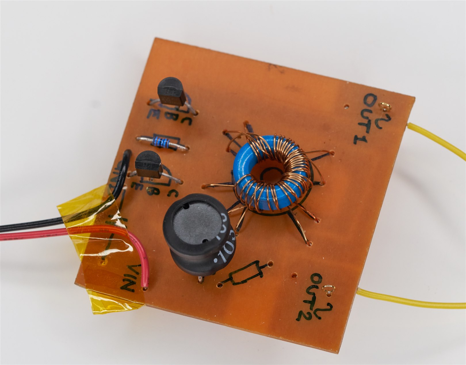
I was experimenting with bits of circuit, hopefully, to become a power supply eventually. It is a work in progress.
At this stage, I’m using bits of scrap copper-clad board, each with a sub-module. It’s too early for a PCB.

However, during the prototyping, I noticed (amongst other issues that I need to solve!) a particular artifact on the ‘scope trace when looking at the output.
This situation ended up being a good example of where it pays to zoom out and look at a lot more of the spectrum view than expected!
Admittedly this was a lot easier to identify using the MXO 4 ‘scope, but it would be possible to spot with other test equipment, such as a spectrum analyzer and a near-field probe. I just used the normal 'scope probe, I didn't do anything special.
With the MXO 4, the anomaly was zoomed in, and then using a logarithmic-frequency spectrum view, it was possible to see the extent of the problem, with the left side of the spectrum view showing the wanted oscillation (fundamental frequency) and its harmonics, and the right side showing the spurious output.

Now I could try to do something about it!
I used tiny ferrite rings (legend has it they were forged by Fair-Rite, part code 2643001501 ) on the base input of the transistors. Essentially, they act as a bit of additional resistance for the higher frequencies. The rings cost $0.02 currently (although more expensive in the UK).

Back to the ‘scope:

Much better!
As mentioned, I still have other problems to deal with, but I thought it was a nice example of why it makes sense to do testing to frequencies far higher than expected, just in case there are spurious emissions, and why it can be a good idea to possess the rings because one never knows when they are needed.
Thanks for reading!


