element14 Community
element14 Community
    Register Log In
  • Site
  • Search
  • Log In Register
  • About Us
  • Community Hub
    Community Hub
    • What's New on element14
    • Feedback and Support
    • Benefits of Membership
    • Personal Blogs
    • Members Area
    • Achievement Levels
  • Learn
    Learn
    • Ask an Expert
    • eBooks
    • element14 presents
    • Learning Center
    • Tech Spotlight
    • STEM Academy
    • Webinars, Training and Events
    • Learning Groups
  • Technologies
    Technologies
    • 3D Printing
    • FPGA
    • Industrial Automation
    • Internet of Things
    • Power & Energy
    • Sensors
    • Technology Groups
  • Challenges & Projects
    Challenges & Projects
    • Design Challenges
    • element14 presents Projects
    • Project14
    • Arduino Projects
    • Raspberry Pi Projects
    • Project Groups
  • Products
    Products
    • Arduino
    • Avnet Boards Community
    • Dev Tools
    • Manufacturers
    • Multicomp Pro
    • Product Groups
    • Raspberry Pi
    • RoadTests & Reviews
  • Store
    Store
    • Visit Your Store
    • Choose another store...
      • Europe
      •  Austria (German)
      •  Belgium (Dutch, French)
      •  Bulgaria (Bulgarian)
      •  Czech Republic (Czech)
      •  Denmark (Danish)
      •  Estonia (Estonian)
      •  Finland (Finnish)
      •  France (French)
      •  Germany (German)
      •  Hungary (Hungarian)
      •  Ireland
      •  Israel
      •  Italy (Italian)
      •  Latvia (Latvian)
      •  
      •  Lithuania (Lithuanian)
      •  Netherlands (Dutch)
      •  Norway (Norwegian)
      •  Poland (Polish)
      •  Portugal (Portuguese)
      •  Romania (Romanian)
      •  Russia (Russian)
      •  Slovakia (Slovak)
      •  Slovenia (Slovenian)
      •  Spain (Spanish)
      •  Sweden (Swedish)
      •  Switzerland(German, French)
      •  Turkey (Turkish)
      •  United Kingdom
      • Asia Pacific
      •  Australia
      •  China
      •  Hong Kong
      •  India
      •  Korea (Korean)
      •  Malaysia
      •  New Zealand
      •  Philippines
      •  Singapore
      •  Taiwan
      •  Thailand (Thai)
      • Americas
      •  Brazil (Portuguese)
      •  Canada
      •  Mexico (Spanish)
      •  United States
      Can't find the country/region you're looking for? Visit our export site or find a local distributor.
  • Translate
  • Profile
  • Settings
Passive Components
  • Technologies
  • More
Passive Components
Forum Please Help with the Identification of this Part
  • Blog
  • Forum
  • Documents
  • Quiz
  • Events
  • Polls
  • Members
  • Mentions
  • Sub-Groups
  • Tags
  • More
  • Cancel
  • New
Join Passive Components to participate - click to join for free!
Actions
  • Share
  • More
  • Cancel
Forum Thread Details
  • Replies 15 replies
  • Subscribers 112 subscribers
  • Views 1691 views
  • Users 0 members are here
Related

Please Help with the Identification of this Part

jw0752
jw0752 over 7 years ago

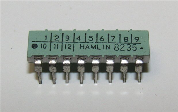
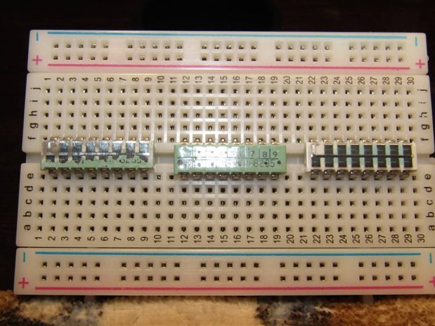
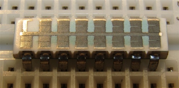
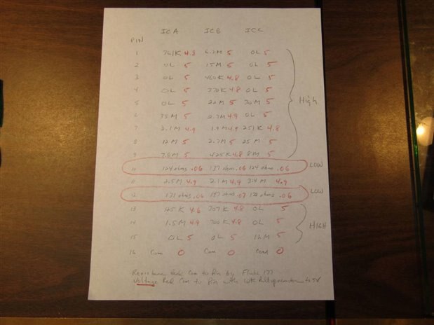
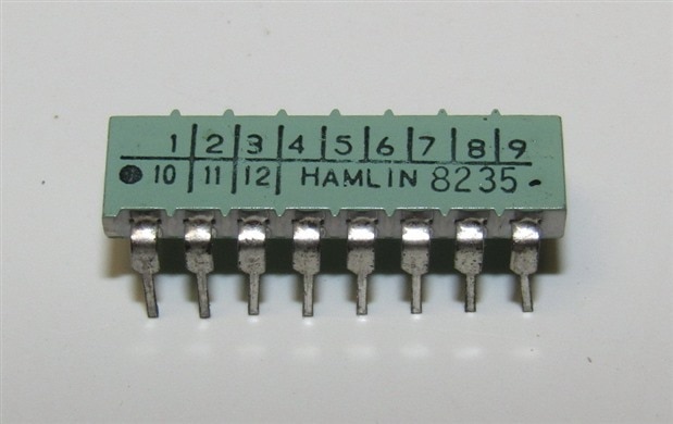
While cleaning out the backroom of an Electronics Store we came across about 100 of these chips. I took them to the shop but I have not been able to determine what they are. Resistance readings are very high and capacitance readings are negligible. Hamlin is now owned by Littlefuse. The 8235 on each appears to be a date code which makes sense as all the other chips that were with this lot all came from the 1970s. Anyone have any ideas. I have tried to Google the image also with no results.


image


Thanks John

  • Sign in to reply
  • Cancel

Top Replies

  • jc2048
    jc2048 over 7 years ago in reply to jw0752 +8
    Perhaps the links were opened with series of high-current pulses.
  • jw0752
    jw0752 over 7 years ago in reply to jc2048 +8
    Hi Jon, I tested your hypothesis by charging a large capacitor to 50 volts and discharging it into three of the 130 ohm links to pins 10 and 12. The resistive links were opened in all cases with almost…
  • jw0752
    jw0752 over 7 years ago +6
    Thank You, Fred27 balearicdynamics mcb1 DaveMcLaughlin , I have taken your advice and I have sacrificed a couple of the components to discover their mystery ID. Once the veneer was removed I could see…
  • DaveMcLaughlin
    DaveMcLaughlin over 7 years ago

    There is no image in your posting so not possible to even know what you are referring to.

    • Cancel
    • Vote Up +1 Vote Down
    • Sign in to reply
    • Cancel
  • jw0752
    jw0752 over 7 years ago in reply to DaveMcLaughlin

    Hi Dave,


    I will try again to post it here.


    image


    John

    • Cancel
    • Vote Up +1 Vote Down
    • Sign in to reply
    • Cancel
  • DaveMcLaughlin
    DaveMcLaughlin over 7 years ago in reply to jw0752

    A nice 1982 vintage part. It does look like a resistor array but how it's configured is unknown.  If you measured side to side, what do you get or maybe Pin 1 to any of the others? The 1 to 12 indicates some kind of SIL type array but in a DIL package.

    • Cancel
    • Vote Up +4 Vote Down
    • Sign in to reply
    • Cancel
  • mcb1
    mcb1 over 7 years ago in reply to jw0752

    I suspect the marking on the top is a reference to a production number or version.

    There are only 8 pins yet the numbers go from 1-9 so it makes no sense.


    I don't suppose you've tried removing the paint or whatever coating it is?


    Nice mystery though.

    Mark

    • Cancel
    • Vote Up +2 Vote Down
    • Sign in to reply
    • Cancel
  • balearicdynamics
    balearicdynamics over 7 years ago in reply to mcb1

    Mark, it is the production month or something similar. It does not go up to 9 but (next row) up to 12 (months). The black pin on the 10 means (suppose) it is the production lot of October.


    Instead I think that HAMLIN 82xx is the model. Maybe a Reed relais array ?


    Enrico

    • Cancel
    • Vote Up +4 Vote Down
    • Sign in to reply
    • Cancel
  • Fred27
    Fred27 over 7 years ago

    If you have 100 then I think one can be sacrificed to some destructive investigation. image

    • Cancel
    • Vote Up +5 Vote Down
    • Sign in to reply
    • Cancel
  • jw0752
    jw0752 over 7 years ago

    Thank You,  Fred27 balearicdynamics  mcb1  DaveMcLaughlin ,


    I have taken your advice and I have sacrificed a couple of the components to discover their mystery ID. Once the veneer was removed I could see that it was laid out as a resistor array.


    image

    Pin 16 comes in as a metal trace that runs down the center of the chips. Laid over the top are black resistive material to each of the remaining 15 pins. Except for the resistive material to pins 10 and 12 the material has been cut with a ? laser on all the other pins. The apparent intent here was not to produce good quality resistors or good quality cuts.. Here is a close up of the chip at the right.


    image

    If you look closely you will see that only Pins 10 and 12 do not show the cut extending across the material. Further the cuts that are across the material of the other pins are poorly done. Actual resistance can range from 200K all the way to OL and none of the readings are stable except the reading on Pins 10 and 12. When I tried to read these unstable resistances with the megger they all showed low resistance at 100 V. None of the resistances, even those on Pins 10 and 12 are consistent from chip to chip. Here is a chart that I made of 3 random chips to show the resistances between the common pin 16 and each of the other pins. The ohm readings are in black.


    image


    Sorry it isn't a little clearer but you can click on it to enlarge it. Note that the common to pin resistance in black is not consistent between chips including the pin 10 and 12 readings. My conclusion at this point was that the actual resistances do not matter as long as there is a large difference between the cut traces and the not cut traces. These chips are a form of cheap factory programmable DIP Shunt. I set up a test circuit where I tied the common of the three chips to ground and then I put a 10K pullup resistor between a 5 volt power supply and my meter DC voltage probe. I then probed each pin on each chip and took the readings and wrote them in red on the chart. All Pins read High (close to 5 volts) except the Pins 10 and 12 on each chip which read 0.06 Volts.


    Perhaps a manufacturer determined that it would be cheaper to order programming shunts in this manner as opposed to using more expensive switches or more labor intensive punch out shunts. The answer is probably lost in the past.


    Thank you to those who responded and gave me the help to pursue this to a more understandable conclusion.


    John

    • Cancel
    • Vote Up +6 Vote Down
    • Sign in to reply
    • Cancel
  • jc2048
    jc2048 over 7 years ago in reply to jw0752

    Perhaps the links were opened with series of high-current pulses.

    • Cancel
    • Vote Up +8 Vote Down
    • Sign in to reply
    • Cancel
  • Problemchild
    Problemchild over 7 years ago in reply to jw0752

    By the looks I think they have been trimmed to be some particular value. The fact they seem to be different makes me wonder if they are just releative to each other or  some such ..hey I'm just guessing!! ;-)

    • Cancel
    • Vote Up +5 Vote Down
    • Sign in to reply
    • Cancel
  • shabaz
    shabaz over 7 years ago in reply to jc2048

    Hi Jon,


    I reckon you're right or extremely close. Because the numbers on the top must be something that people could scratch off, or cover perhaps. They only go to 12 although there are 15 resistors, but since three of the numbers are underneath 1,2 and 3, maybe there was some convention for indicating the higher numbers, or the extra ones were some sort of parity check?

    • Cancel
    • Vote Up +5 Vote Down
    • Sign in to reply
    • Cancel
>
element14 Community

element14 is the first online community specifically for engineers. Connect with your peers and get expert answers to your questions.

  • Members
  • Learn
  • Technologies
  • Challenges & Projects
  • Products
  • Store
  • About Us
  • Feedback & Support
  • FAQs
  • Terms of Use
  • Privacy Policy
  • Legal and Copyright Notices
  • Sitemap
  • Cookies

An Avnet Company © 2025 Premier Farnell Limited. All Rights Reserved.

Premier Farnell Ltd, registered in England and Wales (no 00876412), registered office: Farnell House, Forge Lane, Leeds LS12 2NE.

ICP 备案号 10220084.

Follow element14

  • X
  • Facebook
  • linkedin
  • YouTube