element14 Community
element14 Community
    Register Log In
  • Site
  • Search
  • Log In Register
  • Community Hub
    Community Hub
    • What's New on element14
    • Feedback and Support
    • Benefits of Membership
    • Personal Blogs
    • Members Area
    • Achievement Levels
  • Learn
    Learn
    • Ask an Expert
    • eBooks
    • element14 presents
    • Learning Center
    • Tech Spotlight
    • STEM Academy
    • Webinars, Training and Events
    • Learning Groups
  • Technologies
    Technologies
    • 3D Printing
    • FPGA
    • Industrial Automation
    • Internet of Things
    • Power & Energy
    • Sensors
    • Technology Groups
  • Challenges & Projects
    Challenges & Projects
    • Design Challenges
    • element14 presents Projects
    • Project14
    • Arduino Projects
    • Raspberry Pi Projects
    • Project Groups
  • Products
    Products
    • Arduino
    • Avnet Boards Community
    • Dev Tools
    • Manufacturers
    • Multicomp Pro
    • Product Groups
    • Raspberry Pi
    • RoadTests & Reviews
  • Store
    Store
    • Visit Your Store
    • Choose another store...
      • Europe
      •  Austria (German)
      •  Belgium (Dutch, French)
      •  Bulgaria (Bulgarian)
      •  Czech Republic (Czech)
      •  Denmark (Danish)
      •  Estonia (Estonian)
      •  Finland (Finnish)
      •  France (French)
      •  Germany (German)
      •  Hungary (Hungarian)
      •  Ireland
      •  Israel
      •  Italy (Italian)
      •  Latvia (Latvian)
      •  
      •  Lithuania (Lithuanian)
      •  Netherlands (Dutch)
      •  Norway (Norwegian)
      •  Poland (Polish)
      •  Portugal (Portuguese)
      •  Romania (Romanian)
      •  Russia (Russian)
      •  Slovakia (Slovak)
      •  Slovenia (Slovenian)
      •  Spain (Spanish)
      •  Sweden (Swedish)
      •  Switzerland(German, French)
      •  Turkey (Turkish)
      •  United Kingdom
      • Asia Pacific
      •  Australia
      •  China
      •  Hong Kong
      •  India
      •  Korea (Korean)
      •  Malaysia
      •  New Zealand
      •  Philippines
      •  Singapore
      •  Taiwan
      •  Thailand (Thai)
      • Americas
      •  Brazil (Portuguese)
      •  Canada
      •  Mexico (Spanish)
      •  United States
      Can't find the country/region you're looking for? Visit our export site or find a local distributor.
  • Translate
  • Profile
  • Settings
Power & Energy
  • Technologies
  • More
Power & Energy
Forum Why PWM generate circuit can not adjust the duty cycle to 10%?
  • Blog
  • Forum
  • Quiz
  • Documents
  • Polls
  • Events
  • Mentions
  • Sub-Groups
  • Tags
  • More
  • Cancel
  • New
Actions
  • Share
  • More
  • Cancel
Forum Thread Details
  • Replies 13 replies
  • Subscribers 288 subscribers
  • Views 1603 views
  • Users 0 members are here
  • duty
  • pwm
  • led
  • cycle
  • dimming
Related

Why PWM generate circuit can not adjust the duty cycle to 10%?

Jason
Jason over 15 years ago

I have a problem when I am debuging. My PWM generate circuit can not adjust the duty cycle to 10%! It just 46% when I modulate Rp_Potentiometer.SCH.jpg


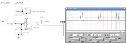
But I have checked the circuit by a software called EWB and the follow images are test result.


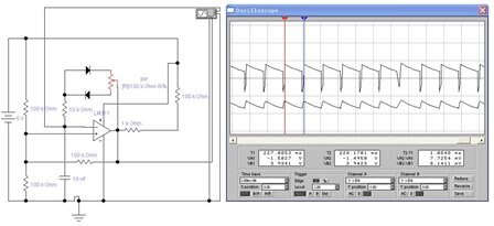
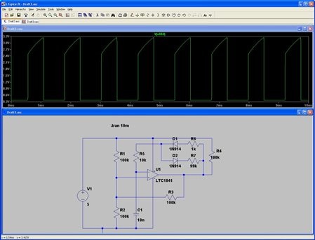
1 R_potentiometer =100k Ohm  100%

   Duty cycle=10%

image


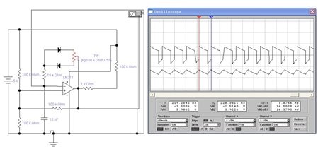
2 R_potentiometer =100k Ohm   50%

   Duty cycle=50%

image


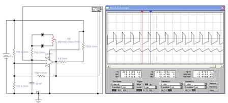
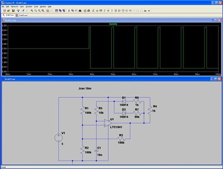
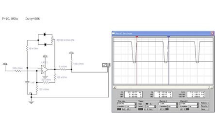
3 R_potentiometer =100k Ohm      0%

   Duty cycle=90%

image


Why? Can anyone tell me why!

  • Sign in to reply
  • Cancel
  • Catwell
    Catwell over 15 years ago

    I've had similar issues with op-amps of the like. I've experienced very spotty results with such circuits. It may just be an innate problem with these chips, but before categorizing it that way, let's try what we can with your setup.


    It could be a multitude of issues. For now we will look at a couple superficial ones.


    It looks like the input or microprocessor may be affecting you amp. Try adding a buffer transistor or op-amp to the output of your PWM signal between it and the input/microprocessor junction. What you'll be making is a voltage follower (unity gain amplifier) that will have no affect of the PWM signal, but will help it from being distorted.


    You might also want to check your resistors actual resistance, or use precision resistors. This check is often overlooked but has profound influence.


    Cabe

    • Cancel
    • Vote Up 0 Vote Down
    • Sign in to reply
    • Cancel
  • albertosombri
    albertosombri over 15 years ago

    Hi guys,


    first of all, which kind of op amp are you using?

    Which is the value of the resistor connected to the anti-parallel diods?

    Try to shunt this resistor.


    Usually the output resistance of any op amp, is quite low, and uP doesn't need to be drived with high current, so I don't think an emitter follower could be a solution.

    In your SW simulation, try to add a scope probe on the capacitor, the real core of the oscillator, and check what happen!

    • Cancel
    • Vote Up 0 Vote Down
    • Sign in to reply
    • Cancel
  • Jason
    Jason over 15 years ago in reply to Catwell

    Hi, Cabe

    Thanks for sharing your experience in solving the AMP problem!

    I have cut the juncture of AMP output and the microprocessor, the problem is still being. So we can see microprocessor is not the cause. And I also checked my components, all of them are normal. Bythe way, my resisitor's tolerance is 1%.


    Jason

    • Cancel
    • Vote Up 0 Vote Down
    • Sign in to reply
    • Cancel
  • Jason
    Jason over 15 years ago in reply to albertosombri

    Hi, Alberto


    My AMP is LM311 Fairchild, and resistor connected to the anti-parallel diods is 10k Ohm--R7, the Potentiometer RP=0~100K Ohm.

    I try to change the value of R7, it only cause the change of output frequency, the duty cycle can not adjust to 10%.

    The following images is the photo of capacitor waveform.


    1,RP_Potentiometer=0%  Duty=90%

    image

    2,RP_Potentiometer=25%  Duty=70%

    image

    3,RP_Potentiometer=50%  Duty=51%

    image

    4,RP_Potentiometer=75%  Duty=30%

    image

    5,RP_Potentiometer=100%  Duty=9%

    image

    • Cancel
    • Vote Up 0 Vote Down
    • Sign in to reply
    • Cancel
  • albertosombri
    albertosombri over 15 years ago in reply to Jason

    The mathematics that rule the frequency of the oscillator, is function of C and the equivalent resistance of R7 and potentiometer.

    So in order to regulate the duty around 1% and 99% you have to adjust the time of charge and discharge of the capacitor.

    When the potentiometer is at 0 position the charge of the capacitor is ruled only by the R7.

    This resistance is just 10% of the potentiometer, and this ratio is just the maximum or the minimum of your duty cycle.

    Teorically, in this calculation, we have to take in account also the resitance of the diods.


    So, try to modify the capacitor value *10 and the potentiometer value 1/10, then put an R7 around 100 ohm, the frequency should remain the same, and you will be able to regulate from 1% to 99%.


    I believe a real circuit with a real scope will be much better instead SW emulation.

    Other capacitor is needed on the mid point of the two 100K resistor, and GND.

    • Cancel
    • Vote Up 0 Vote Down
    • Sign in to reply
    • Cancel
  • michaelkellett
    michaelkellett over 15 years ago

    Hello,


    I have already answered you on this one in the Analogue group where you also asked.


    The LM311 is NOT an op amp - it's a comparator with an OPEN COLLECTOR output.


    It can only sink current not source it. You need a pull up resistor to 5V (I'm assuming that is the value of your Vcc). The resistor should be a low value compared with the load ie which is 10k in your case so the pull up should be 1k.


    If EWB does not correctly simulate the LM311 I suggest you use a simulator that works in future (try LTspice which is a free download at www.linear.com).

    • Cancel
    • Vote Up 0 Vote Down
    • Sign in to reply
    • Cancel
  • albertosombri
    albertosombri over 15 years ago in reply to michaelkellett

    OK,

    the LM311 is not an op amp but it is a comparator, but when you close in a reaction loop a comparator with open collector it appears just like an op amp, then it doesn't need to sink or source high current to uP.


    In order to solve this problem is necessary to focalize on the time of charge and time of discharge of the capacitor, this is the real core of the ocsillator.

    This time is depending by the resistance value, if you are using a 100K potentiometer, the R7 must be 1K if you want to reach 1% and 99%.

    If you will use a R7 of 100 ohm, you can reach 0,1% and 99,9 %.

    I also believe the voltage reference circuit should be improved.


    Alberto.

    • Cancel
    • Vote Up 0 Vote Down
    • Sign in to reply
    • Cancel
  • michaelkellett
    michaelkellett over 15 years ago in reply to albertosombri

    Alberto - you are not quite right about open collector outputs. They can only sink current and not source it. If you refer to the last diagram in Jason's post you see he has resistors of 100k and 1k in series to the 5V supply. When the pot is set to the lower extreme the output of the comparator is trying to charge the capacitor though a 10k resistor - but the only path for current into the capacitor is though the 100k, the 1k and the 10k resistor - that's why the ciruit doesn't work properly. All that is needed is 1k from the output of the comp. to the 5V supply and he will get his 10/90 (approximately) range in duty cycle


    Reducing the feedback fixed resistor to 1k won't help at all.

    • Cancel
    • Vote Up 0 Vote Down
    • Sign in to reply
    • Cancel
  • albertosombri
    albertosombri over 15 years ago in reply to michaelkellett

    Hi Michael,

    Yes, you are completly right about the comparator with open collector, expecially with that polarization, 100K resistence are too high for that device, but the timing problem around the duty cyle is depending by R7 value, and this is not my opinion.

    The frequency (1/T) of the oscillator is coming from the constant time of charge and the constant time of discharge of the capacitors.
    The comparator's output switch from a state to its complement when the voltage on the capacitor reaches the same value of the voltage of other comparator input.


    So:

    T = C * R (during the charge) + C * R (during the discharge)

    T= (C * (Rpot(x)+R7)) + (C * (Rpot(1-x)+R7))


    where:
    T = 1/Foscillator
    C = C4 = 1[nF]
    Rpot = 100[Kohm]
    R7 = 10[Kohm]
    X = potentiometer position ( from 0 to 1, 0% to 100%)


    How you can see, when X=0 and x=1 the only influence on the shorter half periods is due to R7 value.

    • Cancel
    • Vote Up 0 Vote Down
    • Sign in to reply
    • Cancel
  • michaelkellett
    michaelkellett over 15 years ago in reply to albertosombri

    Hello Alberto,


    We can improve your formula to show the effect of the open collector output with 101k pull up:


    T = C * R (during the charge) + C * R (during the discharge) - your formula

    actually there is an additional constant:


    T = K(C * R (during the charge) + C * R (during the discharge)) - K is determined by the values of the bias and feedback on the positive input. Actually even this is not totally accurate because the diodes have an effect but we wont go into that here.


    If we now put in the effect of the OC stage:


         T=  K(C * (Rpot(x)+R7+101k)) + (C * (Rpot(1-x)+R7))


    and the charge period range is:

              K(C* 111k) to K(C*211k)

    the discharge period is:

         K(C* 100k) to K(C*10k)

    so the PW range is 111/(111+100) to 211/(211+10) = 52.6% to 95.5%


    I can't make any sense out of the EWB simulation.


    I've simulated it with LTSpice and used an LTC1841 comaprator (still has open collector style output).

    First with 100k pull up and second with 1k pull up.


    In case the pictures are illegible (they look too small as I'm doing this) I have  attached the jpeg files.


    imageimage
    Attachments:
    image
    image
    • Cancel
    • Vote Up 0 Vote Down
    • Sign in to reply
    • Cancel
>
element14 Community

element14 is the first online community specifically for engineers. Connect with your peers and get expert answers to your questions.

  • Members
  • Learn
  • Technologies
  • Challenges & Projects
  • Products
  • Store
  • About Us
  • Feedback & Support
  • FAQs
  • Terms of Use
  • Privacy Policy
  • Legal and Copyright Notices
  • Sitemap
  • Cookies

An Avnet Company © 2025 Premier Farnell Limited. All Rights Reserved.

Premier Farnell Ltd, registered in England and Wales (no 00876412), registered office: Farnell House, Forge Lane, Leeds LS12 2NE.

ICP 备案号 10220084.

Follow element14

  • X
  • Facebook
  • linkedin
  • YouTube