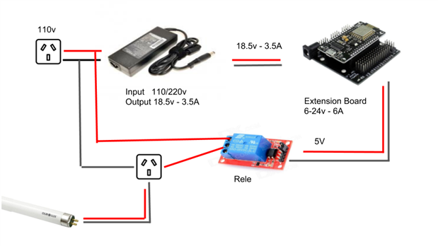
I think my links are correct. but after some successful testing, the extension board eventually burned, which may have failed?
Is there anything wrong with my project?
Your question appears to be missing a lot of detail -
Generally speaking, electronics which get too hot and let out the magic smoke have failed and normally they don't fail for no reason. There's a good chance you may have overstressed something due to poor design, incorrect/accidental connections, improper powering, insufficient cooling, overcurrent/short circuit, etc.
- Gough
my extencion board and a hw-389 for esp8266, which i need and have enough power for 4 sensors + 1 relay that is connected to a 110v outlet. I think the hw-389 should have manufacturing issues. would have some anternativa so that I can have an electrical feed with 4 points 5v and 4 points 3v.
Sorry about my terrible English
I still don't understand what you are trying to do?
The HW-389 is a break-out for the NodeMCU Amica 1.0 ESP8266 board to allow for easier pin connections, along with a barrel plug jack and on-board switchmode converter. If you've burned out the converter, maybe you didn't supply the right voltage (6-24V) or the right polarity (positive center tip is mode common) or short circuited the output (e.g. bad Amica board, bad connections).
How are you connecting the relay? The ESP8266 cannot directly drive a relay - microcontroller pins cannot source high currents and relay coils also produce inductive spikes on turning off which can damage microcontroller outputs. What sort of sensors are you using? How are they connected?
- Gough
I can see you are using an HP laptop power supply with the board - I personally would use something lower voltage because trying to convert 18.5V to 5V would probably result in a fair amount of stress and dissipation in the switching converter of the module. While the module claims to be able to cope with it - I think it's probably not going to be too happy about it and might get a bit hot.
Secondly, I can see you're using a relay module. I'm not familiar with the relay module you are using but it's important to note that the ESP8266 is a 3.3V device and will not produce 5V outputs or tolerate 5V inputs. It seems you are powering the relay module from 5V, which is probably what it requires, but I wonder if the control line might be "pulled up" by the relay module to 5V internally by design and frying your ESP8266 as a result. When mixing devices of different voltages, you have to be very careful to understand how it is designed - if you have a schematic for your relay module, you can confirm whether this is the case (and whether it has the necessary internal MOSFET and protection diode to prevent overloading/damage to the GPIO pin).
- Gough
I suspected that 18.5v would be too much for board. I need to connect 1 neo pixel led with 5v, 1 relay with 5v, and 1 dht11 sensor with 5v, 1 esp8266 with v5, what do you recommend do?
The ESP8266 I/O pins are all 3.3V. If you must interface them with 5V logic, there are a few ways:
- If the ESP8266 is "output only" and the driven device is "input only" - i.e. unidirectional, no pull-up on the driven device, then check if the driven device can handle a lower voltage and still register a high (e.g. 2.5-3.3V). Some devices can, in which case you can directly connect.
- If not, you will need a logic level shifter (one for each data line you are using) - some are unidirectional while others are bidirectional, so buy appropriately. One side will be hooked to 3.3V Vcc for the the ESP8266, the other side will be hooked to 5V Vcc for the 5V devices with the shifter "translating" between levels.
- Depending on the bus, it may be possible to avoid this - e.g. with I2C if you can ensure that there are ONLY pull-ups to 3.3V, then you may be able to get away with it.
But again, you should study the schematics and datasheets of the parts you intend to integrate to see if they can work together or if there are simpler ways of ensuring their compatibility. Applying 5V to the ESP8266 will very quickly cause it to heat up and fail - at the least, you probably will need to look at replacing that if that is what burned.
- Gough
Thank you very much for your attention. I think a good design from a source for arduinos is still pending. I face this difficulty in other projects.