element14 Community
element14 Community
    Register Log In
  • Site
  • Search
  • Log In Register
  • About Us
  • Community Hub
    Community Hub
    • What's New on element14
    • Feedback and Support
    • Benefits of Membership
    • Personal Blogs
    • Members Area
    • Achievement Levels
  • Learn
    Learn
    • Ask an Expert
    • eBooks
    • element14 presents
    • Learning Center
    • Tech Spotlight
    • STEM Academy
    • Webinars, Training and Events
    • Learning Groups
  • Technologies
    Technologies
    • 3D Printing
    • FPGA
    • Industrial Automation
    • Internet of Things
    • Power & Energy
    • Sensors
    • Technology Groups
  • Challenges & Projects
    Challenges & Projects
    • Design Challenges
    • element14 presents Projects
    • Project14
    • Arduino Projects
    • Raspberry Pi Projects
    • Project Groups
  • Products
    Products
    • Arduino
    • Avnet Boards Community
    • Dev Tools
    • Manufacturers
    • Multicomp Pro
    • Product Groups
    • Raspberry Pi
    • RoadTests & Reviews
  • Store
    Store
    • Visit Your Store
    • Choose another store...
      • Europe
      •  Austria (German)
      •  Belgium (Dutch, French)
      •  Bulgaria (Bulgarian)
      •  Czech Republic (Czech)
      •  Denmark (Danish)
      •  Estonia (Estonian)
      •  Finland (Finnish)
      •  France (French)
      •  Germany (German)
      •  Hungary (Hungarian)
      •  Ireland
      •  Israel
      •  Italy (Italian)
      •  Latvia (Latvian)
      •  
      •  Lithuania (Lithuanian)
      •  Netherlands (Dutch)
      •  Norway (Norwegian)
      •  Poland (Polish)
      •  Portugal (Portuguese)
      •  Romania (Romanian)
      •  Russia (Russian)
      •  Slovakia (Slovak)
      •  Slovenia (Slovenian)
      •  Spain (Spanish)
      •  Sweden (Swedish)
      •  Switzerland(German, French)
      •  Turkey (Turkish)
      •  United Kingdom
      • Asia Pacific
      •  Australia
      •  China
      •  Hong Kong
      •  India
      •  Korea (Korean)
      •  Malaysia
      •  New Zealand
      •  Philippines
      •  Singapore
      •  Taiwan
      •  Thailand (Thai)
      • Americas
      •  Brazil (Portuguese)
      •  Canada
      •  Mexico (Spanish)
      •  United States
      Can't find the country/region you're looking for? Visit our export site or find a local distributor.
  • Translate
  • Profile
  • Settings
Power & Energy
  • Technologies
  • More
Power & Energy
Forum Lead acid protection circuit
  • Blog
  • Forum
  • Quiz
  • Documents
  • Polls
  • Events
  • Mentions
  • Sub-Groups
  • Tags
  • More
  • Cancel
  • New
Actions
  • Share
  • More
  • Cancel
Forum Thread Details
  • State Suggested Answer
  • Replies 10 replies
  • Answers 6 answers
  • Subscribers 287 subscribers
  • Views 3033 views
  • Users 0 members are here
Related

Lead acid protection circuit

zagene
zagene over 6 years ago

Hi everyone,

I'm always looking for alternatives for a DC supply, as we have a constant problem with mains supply failure.

Add to this that I am a Ham operator who like to keep things up and running, even on DC power if required.

For DC supply I have the normal AC to DC switch mode supplies but the problem is with a suitable protection for my (very expensive according to me) AGM 12VDC batteries.

If you fail to constantly monitor the AGM battery output voltage or with swapping batteries accidentally (and it do happens if you are in a hurry at night) connect it reverse polarity you have a problem.

I have read many articles on battery protection especially with RPP and current flow back prevention as well as a battery low voltage cut-off so I'm starting a project that is compact and cost efficient enough to add to all my SLA's and AGM (and also all flooded cells for that matter) 12V batteries.

So my circuit is more a combination of several other circuits combining an efficient RPP without to many heat losses as well as combining it with a ATTiny ADC to read the voltage to cut off the battery at a preset low voltage, nothing very extravagant or to large or difficult to populate on a single sided PCB and fit it on the battery output.

My requirements would be to feed a radio or other load with DC at a maximum of 30A @ 13.8VDC (as required by my radio when transmitting.

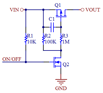
The circuit area I'm not very sure of is the cut-off feed from the ATTiny45 via the 2N7000 that will cut the ground from the main P-ch MOSFET as a high side switch with a maximum current of 55A, Maximum gate voltage of 20V and a RDS(on) of 20mOhm at Vgs of -10VDC.

The second problem may be an Inrush current needed by the load which I do not totally want to limit as in certain instances my radio may require but I have to protect the MOSFET.

The other thing maybe to place a uni directional TVS at the battery poles of the circuit e.g. 1N6377 to clamp high voltage peaks etc.

Please advise me on the following circuit: (its available on PDF format here https://drive.google.com/drive/folders/1jG2ML2XMi52CiVaMMP-QXK-w0ViSZoYC?usp=sharing ) as well as the IRF4905 datasheet

image

  • Sign in to reply
  • Cancel

Top Replies

  • dougw
    dougw over 6 years ago +3 suggested
    Interesting application. You could also use something like an LTC4352 to create an ideal diode which also has under voltage protection. An alternative is LM74700.
  • jw0752
    jw0752 over 6 years ago +2 suggested
    Hi Eugene, You may want to check and verify the polarity of the IRF4905 as in its current config the internal Schottky will conduct current battery to load. As far as the rest of the design I will defer…
  • jw0752
    jw0752 over 6 years ago +2
    Hi Eugene, After reviewing the polarity protection application I believe I was wrong to question the polarity of the IRF 4905. It is correct as you have it. Sorry for the confusion but I have a little…
Parents
  • zagene
    0 zagene over 6 years ago

    Hi Everyone,

    I noted all of your comments and suggestions and this resulted a storm in my mind, thus my late reply.

    John, TY for your suggestions. Regarding the Ideal diode controller (mosfet driver),

    I've researched the component quite a lot in the past few weeks, designed some circuits etc but here is the problem:

    The the LTC4357 or LTC4352 is only locally available trough RS Components and id on my local currency extremely expensive although it is a very nice component and I would certainly like to build my designs around it. The footprint is also very fine and to etch a custom PCB and build it by hand would also present some difficulty. The price of it also make prototyping to expensive as I have learned that just merely calculating values and laying out a PCB do differ from real world conditions. So I just have to do without it (Im also not sure if the gate voltage would drive the available high current MOSFETs in saturation so that may be another hurdle making the design and layout more complex)

    As I went along with this design my ideas became more complex.

    My further question, and quite a nagging one, is would this prevent current flowback from the Battery and the "Charger" if I place a circuit like this between it. I recently lost a power supply that I used for battery maintenance charging at 13.5VDC because (it seems to be) the current flowed back into the PSU when the mains supply failed destroying the PSU or will I have to design another circuit similar to an ideal diode circuit to prevent this?

    My idea is to design a complete battery maintenance system that would utilize inputs from a PV charge controller (maybe an hybrid one for PV and Wind generator supply) to keep the battery charged with the input of the mains charger if the inputs from the DC charge controllers is too low, and thus using the battery system like a DC ups with inputs from mains supply and PV/Wind charger. I hope this make sense.

    We have a huge problem in South Africa with the mains supply (failing and not very constant level) and my (and fellow HAMS) main objective is to keep the communications network running if everything else fails.

    My knowledge is also limited to radio and electronic Hobbyist and DIY'er as I never had the chance to gain expert knowledge in anything.

    John, another thing, limiting the inrush current especially during the radio transmission periods which may require an instant current of up to 20A, would it be something similar like this circuit with Q2 as the 2N22222N2222 or must it be over the combination of the 2N22222N2222 and 2n7000 switch

    image

    What would the influence be on the requirements of the radio during TX as if the supply current and voltage is not adequate it may damage the final PA and or not TX at all.

    Pardon for all this many questions

    Regards

    • Cancel
    • Vote Up +2 Vote Down
    • Sign in to reply
    • Verify Answer
    • Reject Answer
    • Cancel
  • dougw
    0 dougw over 6 years ago in reply to zagene

    If you need to prevent reverse current from flowing through the body diode of a FET, you can use an N-channel FET in series with a P-channel FET.

    • Cancel
    • Vote Up 0 Vote Down
    • Sign in to reply
    • Verify Answer
    • Cancel
  • zagene
    0 zagene over 6 years ago in reply to dougw

    Would something like this work then (I changed the p-channel mosfet to FDS4435BZ for a smaller package for mounting on a PCB that is not wider than a 7A/h SLA wich have a limited output current). The current flow would be then only in one direction preventing current flowback if the input fail.


    image

    • Cancel
    • Vote Up 0 Vote Down
    • Sign in to reply
    • Verify Answer
    • Cancel
Reply
  • zagene
    0 zagene over 6 years ago in reply to dougw

    Would something like this work then (I changed the p-channel mosfet to FDS4435BZ for a smaller package for mounting on a PCB that is not wider than a 7A/h SLA wich have a limited output current). The current flow would be then only in one direction preventing current flowback if the input fail.


    image

    • Cancel
    • Vote Up 0 Vote Down
    • Sign in to reply
    • Verify Answer
    • Cancel
Children
  • michaelkellett
    0 michaelkellett over 6 years ago in reply to zagene

    Forget the ZXGD3112 - it's totally weird, for example fig 4, page 6, needs two additional isolated floating 10V supplies and still ORs the source supplies via the MOSFET drain/source body diode.


    I can't quite decide if your circuit will work, when Input voltage is present U1 will conduct (due to the body diode) so the mid nodeof the MOSFETs will go up to nearly Input voltage.

    If Q2 is on the gate of U1 ispulled low so it turns on and shorts the body diode.

    So the source of U4 is at Input voltage and it's gate is low so it should turn on.


    I would reduce R2 to 10k and increase the 10Rs to 100R.


    To get a good idea of how it will work in practice why don't you use a simulator - LTSpice is free and can do this - don't worry about getting models for the MOSFETs  - just use something similar that's already in the library.


    There are lots of other free simulators.


    MK

    • Cancel
    • Vote Up +2 Vote Down
    • Sign in to reply
    • Verify Answer
    • Reject Answer
    • Cancel
element14 Community

element14 is the first online community specifically for engineers. Connect with your peers and get expert answers to your questions.

  • Members
  • Learn
  • Technologies
  • Challenges & Projects
  • Products
  • Store
  • About Us
  • Feedback & Support
  • FAQs
  • Terms of Use
  • Privacy Policy
  • Legal and Copyright Notices
  • Sitemap
  • Cookies

An Avnet Company © 2025 Premier Farnell Limited. All Rights Reserved.

Premier Farnell Ltd, registered in England and Wales (no 00876412), registered office: Farnell House, Forge Lane, Leeds LS12 2NE.

ICP 备案号 10220084.

Follow element14

  • X
  • Facebook
  • linkedin
  • YouTube