


Hi all
I'm trying to figure out what the best solution for charging a 6V lead acid battery from a 9V peak power / 10.8V O.C circuit solar panel. On cloudy days, the 5W solar panel will put out anything from 20 - 60mA at 6V (tied to the battery). In the winter in some locations, these conditions will persist for weeks at a time, so making the most of the current all of the time rather than making the most when it is sunny is more important.
These are the shortlist of parts:
Linear LT3652 - specifically for solar applications
TI BQ24650EVM-639.BQ24650EVM-639. - specifically for solar applications
TI BQ24450 - shunt regulator for lead acids
TI BQ2031 - switching regulator for lead acids
The Linear LT3652 cannot be used because although the supply current for the chip is listed as 'typically 2.5mA'. It also mentions that the BOOST supply current is typically 20mA, meaning 22.5mA will be wasted before anything gets charged.
The BQ24650EVM-639.BQ24650EVM-639. can't be used because of the current required for it to operate in charging mode. It is listed as 'Adapter supply current' and says typically 25mA. This means on a cloudy day, lots of the energy will be eaten up by the chip.
Am I misinterpreting either of these?
The BQ24450 looks promising. It is a basic shunt regulated design and I have a few questions:
1/ I assume it would require a minimum input voltage of:the battery charging voltage + the diode drop + the transistor / FET drop + the sense resistor(s) drop. I'm planning on charging at no more than 0.8A (with 2 x 5W panels). Can anybody think of any other reason why the BQ24450 would not be suitable for this application?
The BQ2031 also looks like it may be a solution. I have read the application note for MPPT with the bq2031- http://focus.ti.com/lit/an/slva378/slva378.pdf
1/ Apart form the 2mA current draw + transistor drive current, are there any other hidden power requirements from the charging circuit (without MPPT adjustment).
2/ What kind of efficiencies should I expect in my application?
Which of these would you suggest? What other alternatives are there?
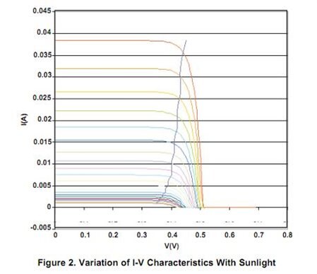
I don't expect using a switching design vs a shunt design to give a large advantage - Assuming full sunlight, a shunt system this utilises approximately 68% of the energy (vs MPP) from the panel charging directly (running at 6V would mean 0.275V / cell vs MPP of 0.42V / cell, so reading off approximately from the chart in this datasheet http://focus.ti.com/lit/an/slva378/slva378.pdf and comparing 0.42 x 0.036 = 0.0152 vs 0.275 x 0.038 = 0.0104 per cell). Switching designs would have to exceed this efficiency figure across the range, especially at the low end.
I am open to other solutions to this problem and any help would be appreciated.
Many thanks
Oli

