element14 Community
element14 Community
    Register Log In
  • Site
  • Search
  • Log In Register
  • About Us
  • Community Hub
    Community Hub
    • What's New on element14
    • Feedback and Support
    • Benefits of Membership
    • Personal Blogs
    • Members Area
    • Achievement Levels
  • Learn
    Learn
    • Ask an Expert
    • eBooks
    • element14 presents
    • Learning Center
    • Tech Spotlight
    • STEM Academy
    • Webinars, Training and Events
    • Learning Groups
  • Technologies
    Technologies
    • 3D Printing
    • FPGA
    • Industrial Automation
    • Internet of Things
    • Power & Energy
    • Sensors
    • Technology Groups
  • Challenges & Projects
    Challenges & Projects
    • Design Challenges
    • element14 presents Projects
    • Project14
    • Arduino Projects
    • Raspberry Pi Projects
    • Project Groups
  • Products
    Products
    • Arduino
    • Avnet Boards Community
    • Dev Tools
    • Manufacturers
    • Multicomp Pro
    • Product Groups
    • Raspberry Pi
    • RoadTests & Reviews
  • Store
    Store
    • Visit Your Store
    • Choose another store...
      • Europe
      •  Austria (German)
      •  Belgium (Dutch, French)
      •  Bulgaria (Bulgarian)
      •  Czech Republic (Czech)
      •  Denmark (Danish)
      •  Estonia (Estonian)
      •  Finland (Finnish)
      •  France (French)
      •  Germany (German)
      •  Hungary (Hungarian)
      •  Ireland
      •  Israel
      •  Italy (Italian)
      •  Latvia (Latvian)
      •  
      •  Lithuania (Lithuanian)
      •  Netherlands (Dutch)
      •  Norway (Norwegian)
      •  Poland (Polish)
      •  Portugal (Portuguese)
      •  Romania (Romanian)
      •  Russia (Russian)
      •  Slovakia (Slovak)
      •  Slovenia (Slovenian)
      •  Spain (Spanish)
      •  Sweden (Swedish)
      •  Switzerland(German, French)
      •  Turkey (Turkish)
      •  United Kingdom
      • Asia Pacific
      •  Australia
      •  China
      •  Hong Kong
      •  India
      •  Korea (Korean)
      •  Malaysia
      •  New Zealand
      •  Philippines
      •  Singapore
      •  Taiwan
      •  Thailand (Thai)
      • Americas
      •  Brazil (Portuguese)
      •  Canada
      •  Mexico (Spanish)
      •  United States
      Can't find the country/region you're looking for? Visit our export site or find a local distributor.
  • Translate
  • Profile
  • Settings
Power & Energy
  • Technologies
  • More
Power & Energy
Forum Need to get MG Electronics Power Supply repaired...or NOT!?
  • Blog
  • Forum
  • Quiz
  • Documents
  • Polls
  • Events
  • Mentions
  • Sub-Groups
  • Tags
  • More
  • Cancel
  • New
Actions
  • Share
  • More
  • Cancel
Forum Thread Details
  • State Suggested Answer
  • Replies 120 replies
  • Answers 51 answers
  • Subscribers 289 subscribers
  • Views 9258 views
  • Users 0 members are here
Related

Need to get MG Electronics Power Supply repaired...or NOT!?

Former Member
Former Member over 10 years ago

Hi.

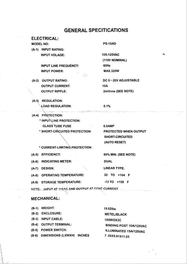
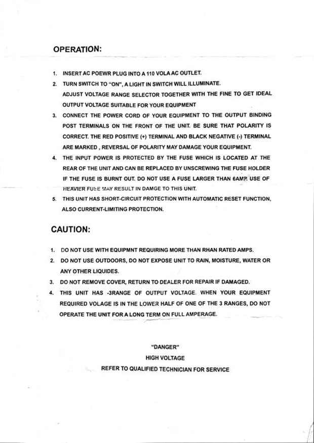
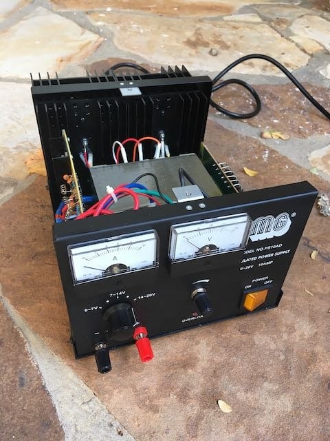
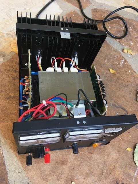
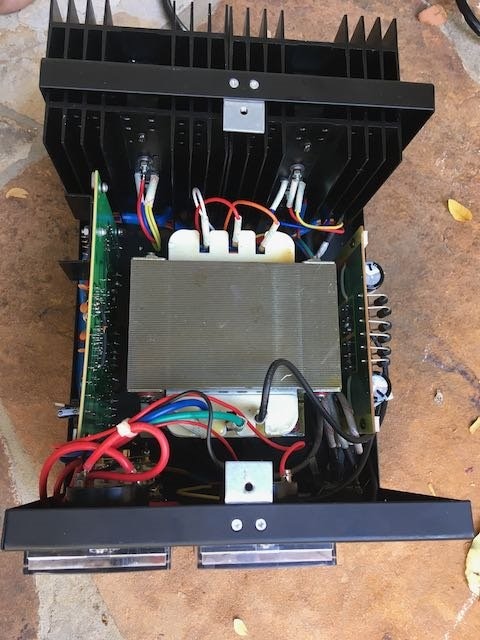
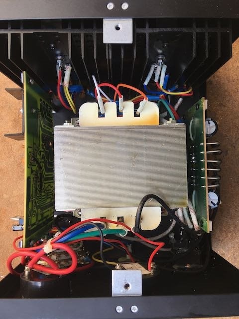
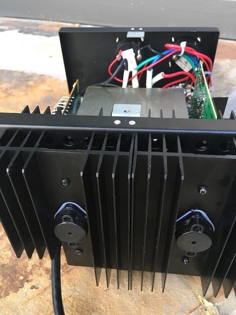
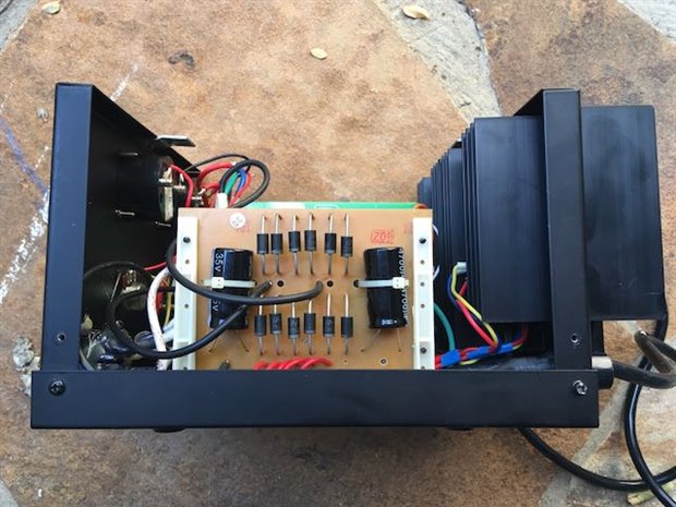
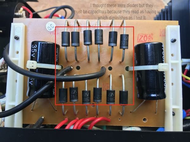
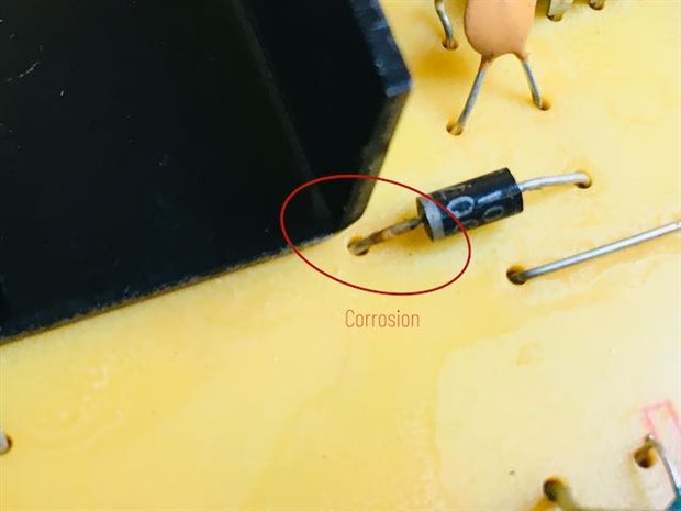
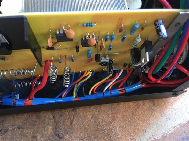
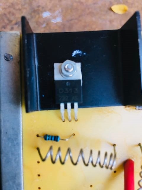
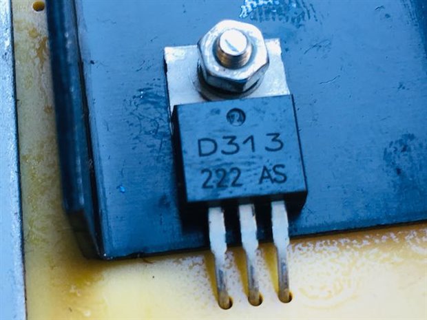
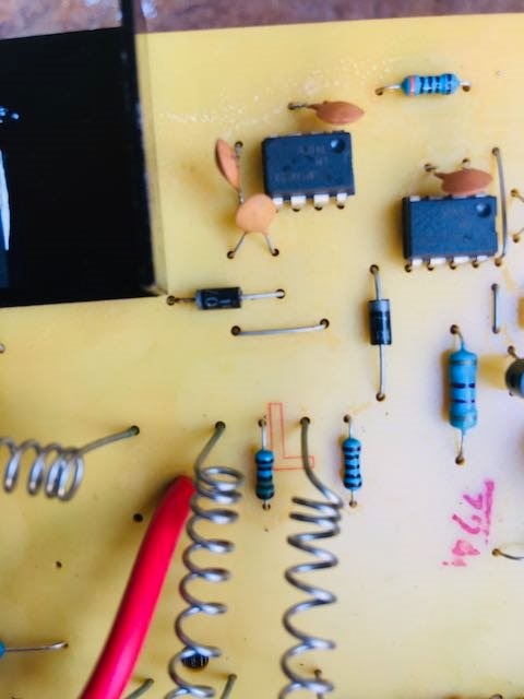
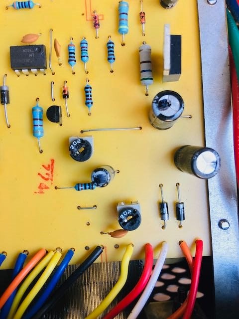
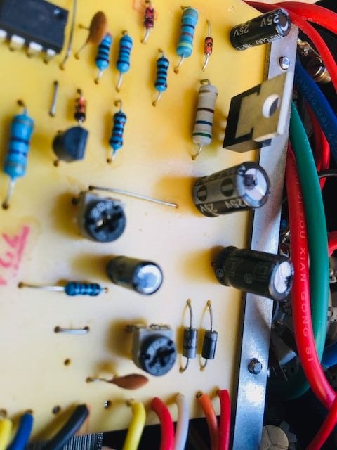
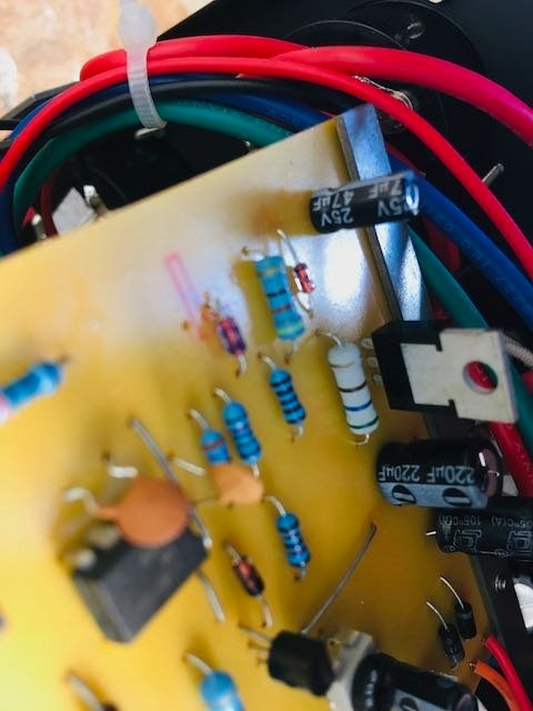
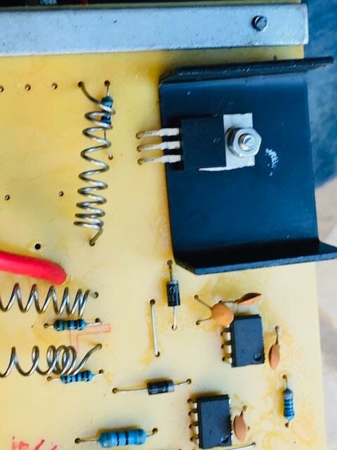
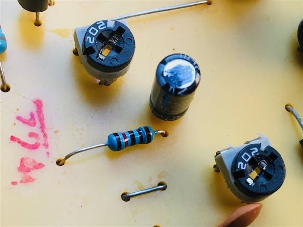
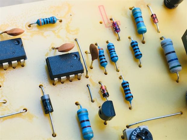
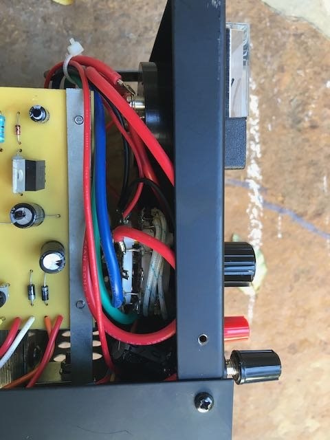
I just bought a lot of Slot Car stuff, yes those cars that go around a track. The guy was serious about his hobby he didn't have the usual wall plug in power pack, he used a MG Electronics PS-10AD, 0-20 VDC at 10 Amps. Well this power supply doesn't work anymore. It does turn on and the red overload light stays on. It doesn't put out anything. I used my multimeter etc., nothing. I know that these are made overseas . They did retail for about $200. So the questions is were can I get it repaired OR should I ? I'm in Western MAss.

I did check the fuse , it's fine. I've got a heavy door stop on my hands, it does have a nice handle and cord on it !

Many thanks for info, Ted


http://www.mgelectronics.com/shopexd.asp?id=179

  • Sign in to reply
  • Cancel

Top Replies

  • mpulliam
    mpulliam over 4 years ago in reply to jw0752 +4 suggested
    Well, I spent all day replacing four 2N3055 transistors....it wasn't easy and... Success!!!
  • mpulliam
    mpulliam over 5 years ago in reply to jw0752 +3
    Hi John, I have a thought. If the output transistors (or is it pass or power transistors?) NTE130 or 2N3055H are giving a bad voltage reading in the voltage test, could it be that any component between…
  • mpulliam
    mpulliam over 4 years ago in reply to mpulliam +3 suggested
    BTW I tested the old 2N3055 transistors, the continuity is the same as a new 2N3055 . There is no continuity between any of the terminals But when I run a diode test, a new 2N3055 tests at .486 volts with…
  • Former Member
    0 Former Member over 10 years ago

    Hi John and others.

    Well I finally put the power supply back together.

    So many tiny washers, lock nuts in a small space, and put back together in the correct order !

    So I grab my multimeter....and then the test lead broke. ....So after a fixed my test leed and tested IT.

    I went to search for continuity across the 2 outputs in front of the power supply, and I did find continuity, so no short!

    So know what to do ?

    Many Thanks, Ted

    • Cancel
    • Vote Up 0 Vote Down
    • Sign in to reply
    • Verify Answer
    • Cancel
  • jw0752
    0 jw0752 over 10 years ago in reply to Former Member

    Hi Ted,

    There may be a typo in your last post. If you found continuity there may be a short. No continuity or only some continuity in one direction is a good sign. If the unit was on my bench I would start to step through the supply checking voltages on stage after stage until it is missing. Then I would look for the problem in that area of the supply. It would be very difficult for anyone to talk you through this process without better documentation and perhaps a little more experience on your part.

    John

    • Cancel
    • Vote Up +1 Vote Down
    • Sign in to reply
    • Verify Answer
    • Reject Answer
    • Cancel
  • Former Member
    0 Former Member over 10 years ago

    Hi Again John.

    No typo...just my stupidity !

    Without access to a real schematic this process is just too much to bear. I think I'm just going to put it on Craigslist and let someone else try to repair it with a better skill set than me !

    Thanks so much for your help and others !

    Ted

    • Cancel
    • Vote Up 0 Vote Down
    • Sign in to reply
    • Verify Answer
    • Cancel
  • mpulliam
    0 mpulliam over 5 years ago

    Hi,

    I have the exact same unit and the exact same problem.  The unit is in pristine condition and will not output a single volt.   I opened it up and it looks perfect.  I have no idea what is wrong, I've used it once.  It worked then, but it won't work now.  The retailer and MG Electronics claim no responsibility -  no refunds, no repairs.


    The fuse is perfect and I put in a new one anyway.  Still nothing... (as confirmed with a multimeter)


    No burn marks, no burn smells... no bulging capacitors - everything is clean and perfect.


    So how do I incremental go about testing likely components to find the culprit?


    Novice electronics guy,

    Matt

    • Cancel
    • Vote Up +1 Vote Down
    • Sign in to reply
    • Verify Answer
    • Cancel
  • jw0752
    0 jw0752 over 5 years ago in reply to mpulliam

    Hi Matt,

    This thread is from several years ago. Don who did a lot of the posting has actually passed away.  If you can follow the posts you can try some of the same things that we recommended before. Unless you have enough experience to do some testing and ask the right questions it will be difficult to trouble shoot remotely. Where are you located just on the chance you are close to one of the guys on the Forum? What type of test instruments do you have? I will try to help you if I can.

    John

    • Cancel
    • Vote Up 0 Vote Down
    • Sign in to reply
    • Verify Answer
    • Reject Answer
    • Cancel
  • mpulliam
    0 mpulliam over 5 years ago in reply to jw0752

    Thanks you John for you quick reply and sorry to hear about Don.   I've read the posts and will start following them, but they never reached a resolution and his problem seems like my problem so far.


    I am currently located in Fort Worth, Texas and sometimes make it to Austin, Texas and to Los Angeles, CA.


    I was once a licensed apprentice electrician, but have no working experience.  I have tinkered with electronics and saw this repair as a project to learn from.

    I understand that capacitors hold a charge.


    I have an Extech EX330 multimeter, a 12v light bulb and test leads,  an Extech MA 12 AC/DC Clamp Meter, and a Klein NCVT-1 Voltage Tester.

    I have a good Weller soldering station.


    My 1st hypothesis of what went wrong (and what to test for) is what would would happen if the unit was at max power and the two output leads touched?


    So far:

    Test #1

    When the unit is plugged into mains A/C and turned on:

    The unit's power switch LED illuminates

    There is no voltage or current indicated in the front panel's amp and volt meters

    There is no voltage or current tested via a multimeter

    There is no light when a load is attached to the output leads (a 12v light)


    Test #2

    The fuse tests positive for continuity (has not blown)

    When the fuse is removed and the unit is turned, the unit's power switch LED does NOT illuminate.


    Test #3

    When the unit is off, the positive and negative output terminals do NOT test positive for continuity.

    When the unit is on, the positive and negative output terminals DO test positive for continuity.


    Any suggestions on what to test next would be appreciated.


    Here's the only documentation on this unit.

    imageimage

    • Cancel
    • Vote Up +1 Vote Down
    • Sign in to reply
    • Verify Answer
    • Reject Answer
    • Cancel
  • jw0752
    0 jw0752 over 5 years ago in reply to mpulliam

    Hi Matt,


    I am in Chippewa Falls, WI. There are guys closer to you but I will let them volunteer if they have time and are able to help.


    I would begin by checking every diode in the unit. You should be able to do most of this testing in circuit. Personally I use a small cheap analog meter so that I can see the needle movement as opposed to a blinking digital read out. What you are looking for is that the meter deflects toward zero ohms when the wires are connected in one direction and doesn't deflect at all in the other. If you get a deflection in both directions you may be dealing with a shorted component but you won't know for sure until you take one side out of the circuit and test it again. If your meter has a diode check on it you could try to use this. Expect no reading in one polarity and a voltage of between 0.7 volts and 0.4 volts in the other. Once again if you get an anomaly you will have to disconnect one side and read the component again.


    Another thing you could check would be to see if the low voltage rail is working. You can do this by reading the power pins on the LM741 ICs.


    image

    As you can see pin 1 is designated on the notch end or from some manufacturers is designated by a dot. Put you meter on DC Volts and take a reading between pin 7 and pin 4. You should have somewhere between 5 and 18 volts is my best guess. This voltage should be present even if the unit has shut down for other problems like an over load condition. For our quest for repair of this unit no voltage would mean we need to trouble shoot the power rail that runs the internal electronics. If we have voltage to the 741s we will have to go looking for a reason the internal brain has decided to shut down the output.


    The fact that we have encountered two of these units with the same problem my indicate that there is a systemic problem in the design.


    Next I would check all the transistors. Don did a good job of explaining this in a previous posting. This technique will apply to all the transistors in the unit. Based on the age I suspect that all the transistors will be regular transistor types. If any of the 3 legged devices have numbers that begin with 78 or 79  example 7805 or 7915 these will be voltage regulators and will not test as transistors. We can however read voltages off of them. With the component label side towards you put the black lead of you DV volt meter on the center pin and then you can read the input voltage on the left pin and the output voltage on the left pin. These devices will be working even if the machine has shut down due to an overload condition.


    With the power turned off you can check resistance across all the capacitors. After the unit has been turned off begin by shorting across the capacitor with a piece of wire. None of these capacitors will have dangerous voltage on them based on the design of the unit. When the unit is working the capacitors will either have the voltage of the service voltage rail likely under 18 volts or at most the voltage of the output of the unit which is probably less than 20 volts. We want to short across the capacitors to protect your meter. When you put the Ohmmeter across the caps you might find a slight reading. You will also likely find a different reading with the meter lead in one polarity as opposed to the other. Put the meter leads on the capacitor. A good indication is a reading that starts low and gradually gets higher. Any reading that starts low and stays low warrants further investigation.


    Come back and give me a report on what you find and we will take the next steps.


    John

    • Cancel
    • Vote Up 0 Vote Down
    • Sign in to reply
    • Verify Answer
    • Reject Answer
    • Cancel
  • jw0752
    0 jw0752 over 5 years ago in reply to mpulliam

    Hi Matt,


    I might mention that Don was a bit hard to read but he was a genius and always expected others to do the work to study and read between the lines. If you have questions on some of his explanations and digressions I will try to interpret. You have picked a great project and if you stick with it you will certainly learn a bit about electronics as well as gaining a power supply if we can just find the gremlin and kick it out of the unit.


    John

    • Cancel
    • Vote Up 0 Vote Down
    • Sign in to reply
    • Verify Answer
    • Cancel
  • jw0752
    0 jw0752 over 5 years ago in reply to mpulliam

    One more thing. While the caps in this unit are safe be aware that the current in the line wiring from the wall through the switch, fuse, and on to the primary of the transformer is lethal!

    • Cancel
    • Vote Up 0 Vote Down
    • Sign in to reply
    • Verify Answer
    • Cancel
  • mpulliam
    0 mpulliam over 5 years ago

    Thank you John for the detailed instructions.


    I will try to attach pictures that I took today.  I think I have a bad diode to start off with. (a camera is a good inspection tool as it turns out)


    I unplugged the unit and performed the diode tests, the LM741 IC tests, and wrote down the measurements in the pictures below.

    I shorted the capacitors and tried to test them but the readings were all over the place, I'm not sure what was going on?

    I haven't tested the transistors yet as the power transistors? in the back of the unit are difficult to get to, unless I could test them from inside the unit?


    Thanks for your help,

    Matt


                    imageimageimageimageimageimageimageimageimageimageimageimageimageimageimageimageimageimageimageimageimageimageimageimageimageimageimageimageimageimageimageimageimageimage

    • Cancel
    • Vote Up 0 Vote Down
    • Sign in to reply
    • Verify Answer
    • Reject Answer
    • Cancel
<>
element14 Community

element14 is the first online community specifically for engineers. Connect with your peers and get expert answers to your questions.

  • Members
  • Learn
  • Technologies
  • Challenges & Projects
  • Products
  • Store
  • About Us
  • Feedback & Support
  • FAQs
  • Terms of Use
  • Privacy Policy
  • Legal and Copyright Notices
  • Sitemap
  • Cookies

An Avnet Company © 2025 Premier Farnell Limited. All Rights Reserved.

Premier Farnell Ltd, registered in England and Wales (no 00876412), registered office: Farnell House, Forge Lane, Leeds LS12 2NE.

ICP 备案号 10220084.

Follow element14

  • X
  • Facebook
  • linkedin
  • YouTube