Chasing a need for a 4.3V supply for a camera and having a couple of MIC29302WUMIC29302WU regulators I decided to solder some bits togther
Following the data sheet, I put 10uF MLCC across input and 22uF Tant across output.
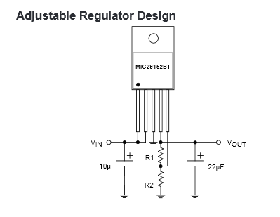
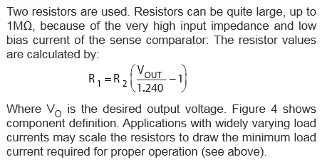
Tied EN to IN and used 4K7 / (11K + 1K variable) to divide OUT across ADJ and GND.
For testing I selected an LED + 330ohm to draw roughly 7mA for required min output current.
Pretty sure my maths is right.
All resistances measure correctly.
Hooked up 5.1V smps (RC bec module + battery) as a supply and checked voltages.
The first LED I used didn't light and I thought it was a dud and replaced it. The second one only just lights.
Nothing gets hot and, as far as I can tell, I haven't let the magic smoke out ... yet.
Measured the following (multimeter, sorry no scope):
Vin: 5.2v
Vout(DC): 2.02v (expecting 4.3V)
Vout(AC): some small mVs possibly MM errror
Vout(Hz): 0
Vout-Vadj: 586mV (expecting 1.24V)
Acknowledging that led + 330 would probably draw slightly less than 7mA, I added 100ohms across output and remeasured:
Vin: 5.2v
Vout: 1.7v
Vout-Vadj: 495mV
Not sure where to look now as every thing measures as expected except anything based on Vout, which seems to measure correctly for the measured vout, but not for the expected vout.
My current thinking is:
- Maybe my divider resistors are too large (but datasheet says some nA value for ADJ current)
- Maybe my choice of caps (I had some) is out. Maybe I put them too close to the device .... I don't really understand too well and followed the datasheet moslty.
- Maybe my dodgey hand soldering of SMDs onto .1 plate through proto board has resulted in unexpected connections.
- Maybe I bumped a short with my MM probe or static zapped the device (both possible) and it's dead. Hoping it's tougher than that.
Thought perhaps OUT(pin4) and ADJ(pin5) were accidentally reversed, but compared circuit and datasheet carefully and it seems correct.
Before I start desoldering stuff, can anyone suggest something else to try?
Thanks
John