element14 Community
element14 Community
    Register Log In
  • Site
  • Search
  • Log In Register
  • Community Hub
    Community Hub
    • What's New on element14
    • Feedback and Support
    • Benefits of Membership
    • Personal Blogs
    • Members Area
    • Achievement Levels
  • Learn
    Learn
    • Ask an Expert
    • eBooks
    • element14 presents
    • Learning Center
    • Tech Spotlight
    • STEM Academy
    • Webinars, Training and Events
    • Learning Groups
  • Technologies
    Technologies
    • 3D Printing
    • FPGA
    • Industrial Automation
    • Internet of Things
    • Power & Energy
    • Sensors
    • Technology Groups
  • Challenges & Projects
    Challenges & Projects
    • Design Challenges
    • element14 presents Projects
    • Project14
    • Arduino Projects
    • Raspberry Pi Projects
    • Project Groups
  • Products
    Products
    • Arduino
    • Avnet Boards Community
    • Dev Tools
    • Manufacturers
    • Multicomp Pro
    • Product Groups
    • Raspberry Pi
    • RoadTests & Reviews
  • Store
    Store
    • Visit Your Store
    • Choose another store...
      • Europe
      •  Austria (German)
      •  Belgium (Dutch, French)
      •  Bulgaria (Bulgarian)
      •  Czech Republic (Czech)
      •  Denmark (Danish)
      •  Estonia (Estonian)
      •  Finland (Finnish)
      •  France (French)
      •  Germany (German)
      •  Hungary (Hungarian)
      •  Ireland
      •  Israel
      •  Italy (Italian)
      •  Latvia (Latvian)
      •  
      •  Lithuania (Lithuanian)
      •  Netherlands (Dutch)
      •  Norway (Norwegian)
      •  Poland (Polish)
      •  Portugal (Portuguese)
      •  Romania (Romanian)
      •  Russia (Russian)
      •  Slovakia (Slovak)
      •  Slovenia (Slovenian)
      •  Spain (Spanish)
      •  Sweden (Swedish)
      •  Switzerland(German, French)
      •  Turkey (Turkish)
      •  United Kingdom
      • Asia Pacific
      •  Australia
      •  China
      •  Hong Kong
      •  India
      •  Korea (Korean)
      •  Malaysia
      •  New Zealand
      •  Philippines
      •  Singapore
      •  Taiwan
      •  Thailand (Thai)
      • Americas
      •  Brazil (Portuguese)
      •  Canada
      •  Mexico (Spanish)
      •  United States
      Can't find the country/region you're looking for? Visit our export site or find a local distributor.
  • Translate
  • Profile
  • Settings
Power & Energy
  • Technologies
  • More
Power & Energy
Forum Maintain power long enough for SBC to power down
  • Blog
  • Forum
  • Quiz
  • Documents
  • Polls
  • Events
  • Mentions
  • Sub-Groups
  • Tags
  • More
  • Cancel
  • New
Actions
  • Share
  • More
  • Cancel
Forum Thread Details
  • Replies 12 replies
  • Subscribers 281 subscribers
  • Views 2249 views
  • Users 0 members are here
  • battery
  • power_supply
Related

Maintain power long enough for SBC to power down

obones
obones over 1 year ago

Hello,

I have connected my 3D printer to an Orange Pi Lite running Octoprint as it is much more user friendly when it comes to managing my prints.
This works just fine but required an additional power source and so I opened the printer and connected the 24V PSU output to a step down converter that provides the 5V for the Orange Pi.
So far, so good, everything is powering up and running properly.

What I'm having an issue with is the power off sequence because when I turn off the printer, the OrangePi is immediately deprived of its power and does not have the time to shutdown properly.
This may lead to some corruption on the file system and most importantly OctoPrint thinks it has crashed and thus starts in "Safe mode" upon the next boot.

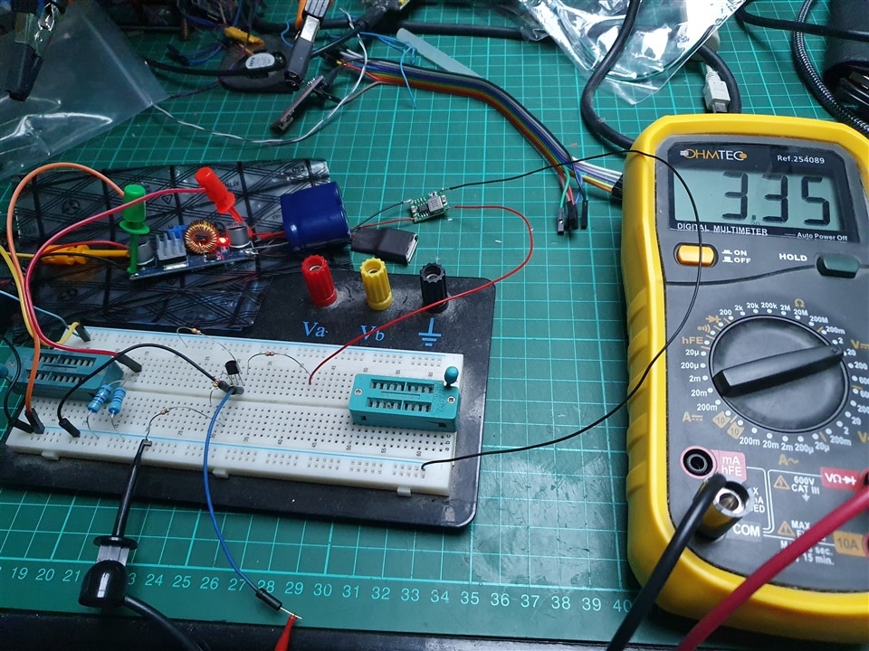
First and foremost, I would need a way to detect the sudden disappearance of power and inform the OrangePi. Looking around for existing resources, I came up with this arrangement using parts that I have sitting on the shelf here:

image

As soon as the 24V is gone, Q1 stops conducting and the Orange Pi sees a logic 1 on one of its GPIO pins.
But I'm not too confident with this because when I usually such an arrangement, the base voltage is usually equal to or smaller than the collector voltage. Here the base voltage is MUCH higher and I'm afraid there would be a situation where the 24V would end up straight into the GPIO pin and frying the entire OrangePi.
So I came up with this design, once again using parts that I already have:

image

It feels wrong to have the same ground on both sides of the optocoupler but it gives me a sense of safety in that the +24V will have a harder time going to the GPIO pins in case of catastrophic failure.

What do you people think of those two options?

And while the above would be easily sorted out, I'm also struggling with the second part of the requirements which would be to maintain the +5V power for a sufficiently long time so that the OrangePi could run a script that properly turns it off.

At first, I took the biggest capacitor that I have here : 3300uF

But this failed miserably, there wasn't much delay in between +24V disappearing and step down converter shutdown.

I should have measured the current it consumes because with 250mA it would have been obvious this capacitor is too small.

So using a capacitor discharge curve calculator, aiming for 4.7V after 20s it showed me that I would need about 20F capacity!

That would cost me anywhere between 10 to 20€ which made me look for other alternatives based on what I have lying around here.

First idea was to use a phone PowerBank that would have its charge port connected to the step down converter and its output to the OrangePi. It's not guaranteed that its output is active while charging, but even then I have a feeling that it would quickly kill the battery to source so much current for so long.

Second idea was to use a 500mA LiPo that I have along with a 3€ controller board like this one:


image

While I know its output is active while charging, it still has the same potential issue of shortening the battery life.

This is why I figured I would need a way to OR the step down converter output with the battery step up converter output.

Easiest way is to use Schottky diodes on both power sources, so this requires 2W diodes and a careful setup of output voltages so that the step down one is higher than the "battery" one to ensure the step down one is used preferentially.

Reading about ORing power sources, I stumbled on Ideal Diodes chips like the LM66100 and LM66200, the latter being a very good candidate as it even shows exactly my use case in its datasheet. Getting my hands on one and being able to solder it is something that I have not even started to consider, though.

In the end, I'm left with those choices:

  1. 20F super capacitor
  2. Inline powerbank / LiPo battery with management board
  3. Side line powerbank with Schottky diodes
  4. Side line powerbank with Ideal diodes

Which option would you recommend?
Do you have any other suggestion?
Are there any potential issues that I did not think of?

Many thanks for your help

  • Sign in to reply
  • Cancel

Top Replies

  • michaelkellett
    michaelkellett over 1 year ago +2
    There is no risk with your single transistor ciruit - so long as R1 (220k) does not fail. The maximum current that can flow from the 24V supply is 24/220 mA = 0.109 mA or 109 uA. The maximum voltage…
  • obones
    obones over 1 year ago +2
    2 months later I was finally able to get some time to experiment with a 10F 5.6V capacitor and the bench power supply, it works! Bear with me for the tidiness, the breadboard setup is in the middle of…
  • michaelkellett
    michaelkellett over 1 year ago in reply to obones +1
    You could do it with one of those motor start switches which are a start and stop push button in a little box. The Start is single pole normally open and the Stop single pole normally closed. You wire…
Parents
  • obones
    obones over 1 year ago

    2 months later

    I was finally able to get some time to experiment with a 10F 5.6V capacitor and the bench power supply, it works!

    Bear with me for the tidiness, the breadboard setup is in the middle of other projects in the works

    image

    The inrush current is quite high (around 3A) but it goes down quite fast after that.

    What's strange (to me), though, is that with a 220k R1 base resistor, the "PowerLoss" voltage is 1.3V when I expected it to be more like 0.6V
    Even stranger, when I replaced R1 with a 100k resistor, the same voltage is now 0.06V which is ten times less the one I expected, but more likely to be picked up as a logical 0.

    Anyway, I'm quite happy with the result, the two 1W resistors simulating the load draw about 250mA and I get more than 20s runtime when 24V is gone so it's really fine!

    Thanks to everyone who commented.

    • Cancel
    • Vote Up +2 Vote Down
    • Sign in to reply
    • Cancel
  • obones
    obones over 1 year ago in reply to obones

    And this now all placed in a neat 3D printed enclosure:

    image

    The open collector is available as a side pin and the pull up resistor is directly placed on the 40pin GPIO connector of the OrangePi, thus avoiding running the 3V3 back to the circuit presented here.

    • Cancel
    • Vote Up +1 Vote Down
    • Sign in to reply
    • Cancel
Reply
  • obones
    obones over 1 year ago in reply to obones

    And this now all placed in a neat 3D printed enclosure:

    image

    The open collector is available as a side pin and the pull up resistor is directly placed on the 40pin GPIO connector of the OrangePi, thus avoiding running the 3V3 back to the circuit presented here.

    • Cancel
    • Vote Up +1 Vote Down
    • Sign in to reply
    • Cancel
Children
No Data
element14 Community

element14 is the first online community specifically for engineers. Connect with your peers and get expert answers to your questions.

  • Members
  • Learn
  • Technologies
  • Challenges & Projects
  • Products
  • Store
  • About Us
  • Feedback & Support
  • FAQs
  • Terms of Use
  • Privacy Policy
  • Legal and Copyright Notices
  • Sitemap
  • Cookies

An Avnet Company © 2025 Premier Farnell Limited. All Rights Reserved.

Premier Farnell Ltd, registered in England and Wales (no 00876412), registered office: Farnell House, Forge Lane, Leeds LS12 2NE.

ICP 备案号 10220084.

Follow element14

  • X
  • Facebook
  • linkedin
  • YouTube