element14 Community
element14 Community
    Register Log In
  • Site
  • Search
  • Log In Register
  • Community Hub
    Community Hub
    • What's New on element14
    • Feedback and Support
    • Benefits of Membership
    • Personal Blogs
    • Members Area
    • Achievement Levels
  • Learn
    Learn
    • Ask an Expert
    • eBooks
    • element14 presents
    • Learning Center
    • Tech Spotlight
    • STEM Academy
    • Webinars, Training and Events
    • Learning Groups
  • Technologies
    Technologies
    • 3D Printing
    • FPGA
    • Industrial Automation
    • Internet of Things
    • Power & Energy
    • Sensors
    • Technology Groups
  • Challenges & Projects
    Challenges & Projects
    • Design Challenges
    • element14 presents Projects
    • Project14
    • Arduino Projects
    • Raspberry Pi Projects
    • Project Groups
  • Products
    Products
    • Arduino
    • Avnet & Tria Boards Community
    • Dev Tools
    • Manufacturers
    • Multicomp Pro
    • Product Groups
    • Raspberry Pi
    • RoadTests & Reviews
  • About Us
  • Store
    Store
    • Visit Your Store
    • Choose another store...
      • Europe
      •  Austria (German)
      •  Belgium (Dutch, French)
      •  Bulgaria (Bulgarian)
      •  Czech Republic (Czech)
      •  Denmark (Danish)
      •  Estonia (Estonian)
      •  Finland (Finnish)
      •  France (French)
      •  Germany (German)
      •  Hungary (Hungarian)
      •  Ireland
      •  Israel
      •  Italy (Italian)
      •  Latvia (Latvian)
      •  
      •  Lithuania (Lithuanian)
      •  Netherlands (Dutch)
      •  Norway (Norwegian)
      •  Poland (Polish)
      •  Portugal (Portuguese)
      •  Romania (Romanian)
      •  Russia (Russian)
      •  Slovakia (Slovak)
      •  Slovenia (Slovenian)
      •  Spain (Spanish)
      •  Sweden (Swedish)
      •  Switzerland(German, French)
      •  Turkey (Turkish)
      •  United Kingdom
      • Asia Pacific
      •  Australia
      •  China
      •  Hong Kong
      •  India
      •  Korea (Korean)
      •  Malaysia
      •  New Zealand
      •  Philippines
      •  Singapore
      •  Taiwan
      •  Thailand (Thai)
      • Americas
      •  Brazil (Portuguese)
      •  Canada
      •  Mexico (Spanish)
      •  United States
      Can't find the country/region you're looking for? Visit our export site or find a local distributor.
  • Translate
  • Profile
  • Settings
Robotics
  • Technologies
  • More
Robotics
Forum Piggy backing Driver Chips?
  • Blog
  • Forum
  • Documents
  • Quiz
  • Events
  • Polls
  • Members
  • Mentions
  • Sub-Groups
  • Tags
  • More
  • Cancel
  • New
Join Robotics to participate - click to join for free!
Actions
  • Share
  • More
  • Cancel
Forum Thread Details
  • Replies 15 replies
  • Subscribers 64 subscribers
  • Views 2370 views
  • Users 0 members are here
Related

Piggy backing Driver Chips?

YT2095
YT2095 over 13 years ago

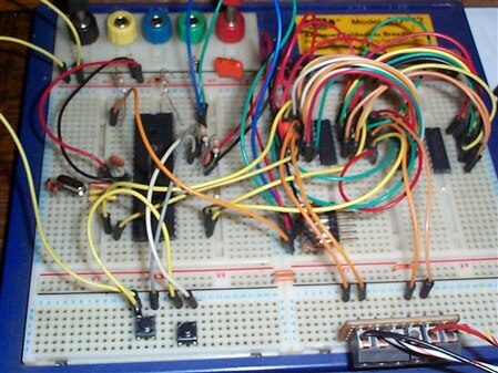
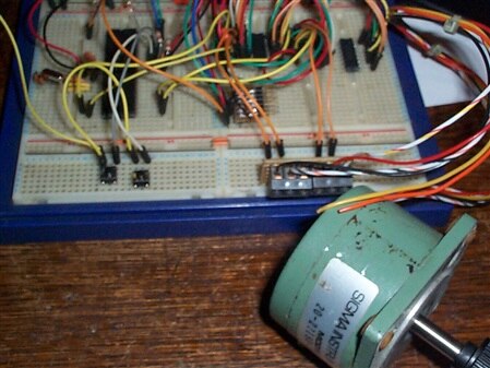
I`m in the building stage of a Robot, and am currently going through my box of assorted stepper motors and hooking them up to circuit I`v built and writen the driver s/ware for.

I`m using the SN754410NESN754410NE dual H-Bridge as the driver.

I have (or rather Had) 10 of them this morning, and have catalogued a good 50% of my motors so far in terms of wiring sequence, there motors range in Current and voltage.

I blew a chip this morning, seems it didn`t like 24v without current protection! LOL

anyway, I have some 1.4A motors and wondered if it`s possible to piggy-back these chips to effectively double the current capacity to 2 Amps?

It won`t be a Physical piggy-back, just simply the pins all connected 1 for 1 on a seperate area of board real estate, each chip with it`s own heatsink.


I can`t see any Technical reason why this shouldn`t be possible, it`s a Digital signal fed in and at a relatively low frequency.


so if any amongst you have any reason Why these 2 chips shouldn`t be married this way, speak now or forever hold your peace! image

  • Sign in to reply
  • Cancel

Top Replies

  • DAB
    DAB over 13 years ago +1
    I think you would have better luck adding a FET or power transister to the output to drive that much current. Putting the two chips together as you suggest will probably not work. If there is any difference…
  • DAB
    DAB over 13 years ago in reply to michaelkellett +1
    Hi Machael, You have to admit, there is a bit of elegance to the circuit. I thought it would not work, but clearly, there is a bit of electronic magic here that begs for more investigation. I love these…
  • DAB
    DAB over 13 years ago

    I think you would have better luck adding a FET or power transister to the output to drive that much current.

    Putting the two chips together as you suggest will probably not work.  If there is any difference (highly likely) between the two chips, one will trigger before the other.  So in a matter of femtoseconds, one will blow out followed by the other.


    Nice try, but silicon if funny that way.  Besides, you should know how to set up a power driver for the motors or get a chip with a higher current rating.


    Just my opinion,


    DAB

    • Cancel
    • Vote Up +1 Vote Down
    • Sign in to reply
    • Cancel
  • YT2095
    YT2095 over 13 years ago in reply to DAB

    Curiosity got the better of me, so I wired up a pair of these chips just to see what would happen anyway.

    and it works exactly the same as with one chip, but the really interesting part is that there is now very little heat generated by either chip anymore.

    before, with just a single chip there was a noticable heating effect after a few mins of run time, and even some heating just on standby without any motor holding current being used, both are cool now image

    it`s unlikely these are matched pairs, as they`re all manufacturer refurbished chips from China, and although the date codes are identical, the ejector pin markings on the bottom aren`t.


    maybe it has something to do with it only running at 8mS per step?

    • Cancel
    • Vote Up 0 Vote Down
    • Sign in to reply
    • Cancel
  • DAB
    DAB over 13 years ago in reply to YT2095

    Well I am truely impressed.  I would have thought they would have burned up, but if your technique actually worked, then that could be very useful for future design projects.

    Could you post some pictures of your setup?  I may want to play with the circuit to drive some motors.


    I have a thousand questions about what is really going on with the two chips, but they are better saved until I can think about it for a while to see if I can fully understand what is going on between the two chips.


    Really neat concept.  I wonder why nobody ever tried this before.


    As for the step speed, I would be interested if you can run at higher rates, but I am not sure you want to risk your setup.  Could be an interesting experiment though.


    Thanks,

    DAB

    • Cancel
    • Vote Up 0 Vote Down
    • Sign in to reply
    • Cancel
  • YT2095
    YT2095 over 13 years ago in reply to DAB

    Sure, I`ll include some pictures, although it May not be any clearer from them what`s what exactly as there`s a load of wires in the way:


    image


    Breifly, on the far left is the PIC 16F877A that I`m using to prototype my code on, eventually this code will go onto a 16C57 chip, the 2 switches left front are Motor direction, there`s also Direction Inhibit resistors on the chip to keep pins 6,7 on portB low, if one goes High (a limit switch activates) then it stops movement in that direction..

    the 2 chips on the right are both H-Bridge drivers wired pin for pin to each other, front right is a simple breakout board because some steppers have wires too thick to fit into breadboard.

    the array of 6 pins in the middle of the board is so I plug my PICKIT2 programer into it.


    image


    this is One of the steppers I`m using on it, ignore those 2 wires (Org, Yel) they`re not used in the Bipolar implementation.


    I altered the step speed this morning and it changed nothing with regards to heating, I went up to 3mS delay which is the limit on all my motors so far anyway.


    as for it not being done before, I`v no idea? maybe there is some sort of unknown problem with the idea that I`v not found yet, but for Now, I must admit to being perfectly happy with it and will certainly be using it.

    I had very little to lose by trying it and I know the PIC chip is capable of driving 2 of them (they have a pretty good mA rating per pin for fanout).


    for any interested, here`s the code so far:


    ;Chip Settings

    #chip 16F877A,4

    #config BODEN=ON, WDT=OFF, OSC=HS


    delay=10

    dir portb in

    dir portd out

    start:

    If portb.0 =1 then

        gosub anticlk

    End If

    If portb.1 =1 then

        gosub clock

    End if

    portd=0

    goto start:

    anticlk:

    If portb.6 =1 then

        goto start

    End If

    portd = 9

    wait delay ms

    portd = 5

    wait delay ms

    portd = 6

    wait delay ms

    portd = 10

    wait delay ms

    return

    clock:

    If portb.7=1 then

        goto start

    End If

    portd = 10

    wait delay ms

    portd = 6

    wait delay ms

    portd = 5

    wait delay ms

    portd = 9

    wait delay ms

    return

    • Cancel
    • Vote Up 0 Vote Down
    • Sign in to reply
    • Cancel
  • michaelkellett
    michaelkellett over 13 years ago in reply to YT2095

    Hello YT,


    Putting these parts in parallel is a very bad idea for anything other than a quick hack. Because they contain built in thermal protection it is possible for one device to shut down when it gets hot, this will leave the other to do all the work, so if you are lucky it will shutdown very quickly. There is nothing to ensure that the load is shared equally. You could improve matters by putting resistors in series with the drivers (about 0.5R seems about right) but for a reliable soultion you should get drivers that can cope with the current.


    Michael Kellett

    • Cancel
    • Vote Up 0 Vote Down
    • Sign in to reply
    • Cancel
  • DAB
    DAB over 13 years ago in reply to michaelkellett

    Hi Machael,


    You have to admit, there is a bit of elegance to the circuit.  I thought it would not work, but clearly, there is a bit of electronic magic here that begs for more investigation.  I love these "it shouldn't work" ideas that prove everything you thought you knew about circuit design wrong.


    It also sparks the old what else can we do differently with circuits that we thought were impossible.

    Eitherway, it is a tinkerers curiosity for now and it is just plain cool.


    Just my opinion,

    DAB

    • Cancel
    • Vote Up +1 Vote Down
    • Sign in to reply
    • Cancel
  • michaelkellett
    michaelkellett over 13 years ago in reply to DAB

    Hello Dab,


    What bothers me is that it looks like the kind of thing that will work on breadboard but less well in real life on a pcb - the breadboard will introduce quite a bit of extra resistance in the ciruit which will improve the current sharing between the chips. Using power transistors in parallel is nothing new but any reputable design I have seen uses current sharing resistors. With current sharing resistors the 7544410s should be OK but quite abit of power must be wasted in the resistors. Lower value resistors can be used if the drivers are matched for voltage drop at working current.

    The bad thing (with these drivers) is that if the chips get hot then the built in protection will turn one of them off leaving the other to carry all the current - this might be OK but would need careful verification.


    Michael Kellett

    • Cancel
    • Vote Up 0 Vote Down
    • Sign in to reply
    • Cancel
  • YT2095
    YT2095 over 13 years ago in reply to michaelkellett

    I think what helps a little in this particular cct, is the fact that the 5v PSU is only rated at 1.5A, but more importantly that a Single driver chip will run these motors, just not very comfortably and Do get quite hot on their own, a situation that stop when paired up.

    I have put in a couple of .5R resistors on the Motor Drives + rail anyway as I agree that it`s always a good idea to have buffer that helps balance inequalities.


    I`v tried a variety of On-Fail scenarios with these chips and haven`t popped one yet, consisting mainly of pulling out one wire at a time and testing for heat, and then moving on to the next wire etc...

    it seems to be a remakably robust little curiosity!


    I think perhaps the next stage should be to put onto a board and test it from there, and add some Reverse biased diodes across the  Motor wires to protect against back emf spikes, yeah, I don`t even have any of those in yet!


    and if I stay with the 16F877A (I have dozens of them anyway) I have all of PortA with it`s analog pins to monitor any heating of the chips as well image

    • Cancel
    • Vote Up 0 Vote Down
    • Sign in to reply
    • Cancel
  • DAB
    DAB over 13 years ago in reply to michaelkellett

    Hi Michael,


    Yes, I remember when some of the high power audio amps came out in the 1970's with dozens of power transisters in parallel.

    Sure enough, as soon as one failed, the whole batch would go in a microsecond or less.

    So I agree in your advice to avoid doing it without the proper circuit design to limit overdrive conditions and a fail safe current shunt.


    However, I do like the idea for a low risk circuit on the cheap.  I am surprised we have not seen this practice put out by some of the knockoff companies.


    Thanks for the interesting discussions.  This topic has been a fun diversion.


    DAB

    • Cancel
    • Vote Up 0 Vote Down
    • Sign in to reply
    • Cancel
  • YT2095
    YT2095 over 13 years ago in reply to michaelkellett

    after some thought about your objections, and the way that wiring this board happened to turn out purely by accident, I think I have a solution!

    on this board it would save a LOT of extra wiring if I put One phase on one chip and the other phase on the other chaip, rather than have 2 phases on each chip.

    therefore Should there be any heat discrepancy between one phase and the other, being on the same die, the chip simply shuts down a Phase, and doesn`t have to be trying to Half work the other phase at the same time.

    so even if one chip entirely overheats or shuts down, it`ll not effect the other, but I still get the 2x Current! image

    I can`t think of any other way to get a better thermal intimacy and matching than this.


    what do you think?

    • Cancel
    • Vote Up 0 Vote Down
    • Sign in to reply
    • Cancel
>
element14 Community

element14 is the first online community specifically for engineers. Connect with your peers and get expert answers to your questions.

  • Members
  • Learn
  • Technologies
  • Challenges & Projects
  • Products
  • Store
  • About Us
  • Feedback & Support
  • FAQs
  • Terms of Use
  • Privacy Policy
  • Legal and Copyright Notices
  • Sitemap
  • Cookies

An Avnet Company © 2025 Premier Farnell Limited. All Rights Reserved.

Premier Farnell Ltd, registered in England and Wales (no 00876412), registered office: Farnell House, Forge Lane, Leeds LS12 2NE.

ICP 备案号 10220084.

Follow element14

  • X
  • Facebook
  • linkedin
  • YouTube