element14 Community
element14 Community
    Register Log In
  • Site
  • Search
  • Log In Register
  • Community Hub
    Community Hub
    • What's New on element14
    • Feedback and Support
    • Benefits of Membership
    • Personal Blogs
    • Members Area
    • Achievement Levels
  • Learn
    Learn
    • Ask an Expert
    • eBooks
    • element14 presents
    • Learning Center
    • Tech Spotlight
    • STEM Academy
    • Webinars, Training and Events
    • Learning Groups
  • Technologies
    Technologies
    • 3D Printing
    • FPGA
    • Industrial Automation
    • Internet of Things
    • Power & Energy
    • Sensors
    • Technology Groups
  • Challenges & Projects
    Challenges & Projects
    • Design Challenges
    • element14 presents Projects
    • Project14
    • Arduino Projects
    • Raspberry Pi Projects
    • Project Groups
  • Products
    Products
    • Arduino
    • Avnet & Tria Boards Community
    • Dev Tools
    • Manufacturers
    • Multicomp Pro
    • Product Groups
    • Raspberry Pi
    • RoadTests & Reviews
  • About Us
  • Store
    Store
    • Visit Your Store
    • Choose another store...
      • Europe
      •  Austria (German)
      •  Belgium (Dutch, French)
      •  Bulgaria (Bulgarian)
      •  Czech Republic (Czech)
      •  Denmark (Danish)
      •  Estonia (Estonian)
      •  Finland (Finnish)
      •  France (French)
      •  Germany (German)
      •  Hungary (Hungarian)
      •  Ireland
      •  Israel
      •  Italy (Italian)
      •  Latvia (Latvian)
      •  
      •  Lithuania (Lithuanian)
      •  Netherlands (Dutch)
      •  Norway (Norwegian)
      •  Poland (Polish)
      •  Portugal (Portuguese)
      •  Romania (Romanian)
      •  Russia (Russian)
      •  Slovakia (Slovak)
      •  Slovenia (Slovenian)
      •  Spain (Spanish)
      •  Sweden (Swedish)
      •  Switzerland(German, French)
      •  Turkey (Turkish)
      •  United Kingdom
      • Asia Pacific
      •  Australia
      •  China
      •  Hong Kong
      •  India
      •  Korea (Korean)
      •  Malaysia
      •  New Zealand
      •  Philippines
      •  Singapore
      •  Taiwan
      •  Thailand (Thai)
      • Americas
      •  Brazil (Portuguese)
      •  Canada
      •  Mexico (Spanish)
      •  United States
      Can't find the country/region you're looking for? Visit our export site or find a local distributor.
  • Translate
  • Profile
  • Settings
Robotics
  • Technologies
  • More
Robotics
Forum How do I monitor an angle?
  • Blog
  • Forum
  • Documents
  • Quiz
  • Events
  • Polls
  • Members
  • Mentions
  • Sub-Groups
  • Tags
  • More
  • Cancel
  • New
Join Robotics to participate - click to join for free!
Actions
  • Share
  • More
  • Cancel
Forum Thread Details
  • Replies 17 replies
  • Subscribers 66 subscribers
  • Views 2518 views
  • Users 0 members are here
  • sensors
  • measure_angles
  • absolute_position
Related

How do I monitor an angle?

Former Member
Former Member over 12 years ago

Hi all,


To say that I am new to robotics would be an understatement.  My first "mini project" is putting a camcorder on a turntable-style bearing.  The turntable has (will have) wires fed through the center, so I would like to limit the movement of the turntable to 360 degrees in order to avoid twisting up the wires.  I would also like to be able to find out the exact angle in which the camcorder is pointing so that I can chart the angle in an application.  From the searches I've done, it seems like the right tool is a absolute position encoder.  Am I on the right track?  Can anyone recommend a good product that I could use in conjunction with a turntable?


Thanks!

  • Sign in to reply
  • Cancel

Top Replies

  • DAB
    DAB over 12 years ago +1
    You can buy 360 degree turning potentiometers, or you could use encoders, accelerometers or a simple led/detector and place a grey scale strip of paper around the turntable base. You set up the scale so…
  • TaylorTronics
    TaylorTronics over 12 years ago

    the fastest way to get this going would be to fix a 50k to 250k linear pot to the turntable and connect it to the resistance input of a data logger. i did a quick search of farnells and found a pico technology USB DrDA VERSATILE DATA ACQUISITION unit. goto au.element14.com/data-acquisition_data-logging

    the pot wont quite do 360 but start messing with optical position sensors and you might get bogged down

    hows that

    • Cancel
    • Vote Up 0 Vote Down
    • Sign in to reply
    • Cancel
  • DAB
    DAB over 12 years ago

    You can buy 360 degree turning potentiometers, or you could use encoders, accelerometers or a simple led/detector and place a grey scale strip of paper around the turntable base.  You set up the scale so that it gives separate values for each degree.  Just about any graphics program will print you a strip to the correct change.  You could also use tic marks on a paper, but you need to have a zero angle point and keep active track of going right or left to keep track of your position.


    Basically, you just need to define how much accuracy you need and repeatability you need and then find a solution that works.


    Engineering 101.


    DAB

    • Cancel
    • Vote Up +1 Vote Down
    • Sign in to reply
    • Cancel
  • TaylorTronics
    TaylorTronics over 12 years ago

    the grey scale strip is a good idea. i have developed a simple circuit to drive a led / opto-transistor reflective detector. it is reasonably immune to ambient light and has high sensitivity. ill give details if anyone is interested. (although there are plenty of chips out there that will do the job nicely, and can be hooked directly to a cpu / mpu)

    • Cancel
    • Vote Up 0 Vote Down
    • Sign in to reply
    • Cancel
  • Ramu
    Ramu over 12 years ago

    I would use a liner rotary potensiometer or some encode. Potensiometer is much cheaper. It would be good to use multiturn one. ten You'll ne able to mesure all 360 deg. As for fizical limitation can use something like spring with limiting sides. and a slider or a stick sliding just 360 deg.  do not know how to explane it
    I have drawned a ruf skech... As you see I'm not so good with paint imageimage

    • Cancel
    • Vote Up 0 Vote Down
    • Sign in to reply
    • Cancel
  • Ramu
    Ramu over 12 years ago in reply to Ramu

    By the way for mesuring the angle I'd use arduino. image

    • Cancel
    • Vote Up 0 Vote Down
    • Sign in to reply
    • Cancel
  • Former Member
    Former Member over 12 years ago in reply to DAB

    Hi DAB,


    I think I liked your idea about having a grayscale ring (I'm attaching a file I created based on how I interpreted your reply).  I do have a follow-up question: If I at some point put a night-vision camera on the turntable, would the grayscale ring approach still work?  If not, maybe taking the linear potentiometer approach would be the better route.  The biggest problem I'm seeing right now with the linear pot (as described by Peter and Raimondas) is that I'm still unclear how to attach it.  My current design has a vertical "drive" shaft coming through the center of the turntable and it's getting in the way of how I thought the linear pots would attach.  Maybe I should just order a couple different kinds and play around with it.


    Thanks.

    image

    • Cancel
    • Vote Up 0 Vote Down
    • Sign in to reply
    • Cancel
  • Ramu
    Ramu over 12 years ago in reply to Former Member

    You mean you have connected a turntable directly to the motor? What type of mottor is it? You do not use any dears? you could use some gears to make the potensiometer turn when the table turns. And then you can ujust gera ratio (size ot table gear / size of potensiometer gear) to get the maximum acuracy of your potensiometer. For example if you have potensiometer that is turning less then 360 deg, just 270 deg for axample. then you can chose the gear ratio to be about 0.7 then 360 def of table rotation will turn 252 deg for potensiometer. And you'll have spare 18 deg not to breack it. image and still have a good resolution.

    As for connectin potensiometer and mesuring its resistens, you can use arduino analog input. And if you controll talbes rotation motor with arduino, then it will be perfect.


    So what  will control the turning motor and what wil send comands were to turn? Is it pc over usb or what? image


    By the way, do you know how to connect potensiometer for mesuting it?

    • Cancel
    • Vote Up 0 Vote Down
    • Sign in to reply
    • Cancel
  • DAB
    DAB over 12 years ago in reply to Former Member

    If you set up a LED and light detector over the ring, it would work in any lighting condition as it is only focused on the ring.

    You determine position by measuring the amount of reflectance from the ring based upon the level of grey that the detector sees.


    You can use gears to turn a potentiometer or an encoder to measure movement.  It all depends upon how much you intend to move and how accurate you need to know the position.


    Attaching the encoding device depends on access and resolution.  Most application would use the encoder on the primary turning access with a reset when you go 360 degrees.  However, you can use a series of gears or other connections and derrive your position from the movement of the table.  Again, accuraccy and repeatability will drive you to the best solution.


    Have fun,

    DAB

    • Cancel
    • Vote Up 0 Vote Down
    • Sign in to reply
    • Cancel
  • Ramu
    Ramu over 12 years ago in reply to DAB

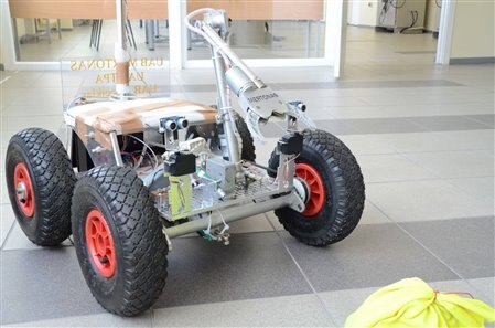
    Yes it depends on how acurat you want it to mesure. As for axample for this robot:
    image

    For hand position we ussed 2 regular potensiometers. It is not even a liner potensiometer, but still does the trick.

    • Cancel
    • Vote Up 0 Vote Down
    • Sign in to reply
    • Cancel
  • TaylorTronics
    TaylorTronics over 12 years ago

    Yes DAB, define your resolution and develop from there (the three D's - define, define, define). Back to the point of ambient light. Let's assume a high resolution. Using a grey scale ring (presumebly going from black to white along its circumference) and a calibrated reflective led/opto-transistor unit with an optimal focal distance of 5 mm, we will need an interface that will produce an analog voltage that represents the amount of light reflected from the ring (not necessarily linear, it can be calibrated using a lookup table) that will be run into an A/D converter (say 16 bit). Now lets assume our opto unit is sufficiently focused to detect changes in light down to 64,000 parts over the rings circumference (how many pixels does the focal area cover and how many pixels are on the ring). The problem is: changes in ambient light will add an unknown constant error to our voltage, and our reading, and may saturate our opto-transistor under extreme lighting conditions.  If we use a simple resistor / common emmiter setup, we can increase our gain and sensitivity by increasing our resistance, but the transistor will saturate under lower ambient. Or, we can minimise this effect by using a lower resistance, but we sacrifice gain / sensitivity. Saturation has been my biggest problem. In fact, manufacturers go to a great deal of trouble to account for / remove these effects in their interface circuits.

    Of course, there are several ways around this:

    1: Use a pot. Simple, but they are prone to wear and tear and dirt. Also, start messing with gears and it can get messy.

    2: Enclose the unit in a light proof enclosure. Good option, but this adds to the mechanical complexity.

    3: Buy a matched detector / interface from farnells. The simplest, but where's the fun factor.

    4: Develope your own interface. I have done this and it is a fantastic learning experience if you see it through (it took me years, and the deeper I looked into it, the more satasfying and rewarding it became. I got a real buzz every time I found an improvement or a more elegent solution).

    By the way, feedback is always good and my ratings go up (LOL), keep it coming! (cool robot Raimondus) image

    • Cancel
    • Vote Up 0 Vote Down
    • Sign in to reply
    • Cancel
>
element14 Community

element14 is the first online community specifically for engineers. Connect with your peers and get expert answers to your questions.

  • Members
  • Learn
  • Technologies
  • Challenges & Projects
  • Products
  • Store
  • About Us
  • Feedback & Support
  • FAQs
  • Terms of Use
  • Privacy Policy
  • Legal and Copyright Notices
  • Sitemap
  • Cookies

An Avnet Company © 2025 Premier Farnell Limited. All Rights Reserved.

Premier Farnell Ltd, registered in England and Wales (no 00876412), registered office: Farnell House, Forge Lane, Leeds LS12 2NE.

ICP 备案号 10220084.

Follow element14

  • X
  • Facebook
  • linkedin
  • YouTube