element14 Community
element14 Community
    Register Log In
  • Site
  • Search
  • Log In Register
  • About Us
  • Community Hub
    Community Hub
    • What's New on element14
    • Feedback and Support
    • Benefits of Membership
    • Personal Blogs
    • Members Area
    • Achievement Levels
  • Learn
    Learn
    • Ask an Expert
    • eBooks
    • element14 presents
    • Learning Center
    • Tech Spotlight
    • STEM Academy
    • Webinars, Training and Events
    • Learning Groups
  • Technologies
    Technologies
    • 3D Printing
    • FPGA
    • Industrial Automation
    • Internet of Things
    • Power & Energy
    • Sensors
    • Technology Groups
  • Challenges & Projects
    Challenges & Projects
    • Design Challenges
    • element14 presents Projects
    • Project14
    • Arduino Projects
    • Raspberry Pi Projects
    • Project Groups
  • Products
    Products
    • Arduino
    • Avnet Boards Community
    • Dev Tools
    • Manufacturers
    • Multicomp Pro
    • Product Groups
    • Raspberry Pi
    • RoadTests & Reviews
  • Store
    Store
    • Visit Your Store
    • Choose another store...
      • Europe
      •  Austria (German)
      •  Belgium (Dutch, French)
      •  Bulgaria (Bulgarian)
      •  Czech Republic (Czech)
      •  Denmark (Danish)
      •  Estonia (Estonian)
      •  Finland (Finnish)
      •  France (French)
      •  Germany (German)
      •  Hungary (Hungarian)
      •  Ireland
      •  Israel
      •  Italy (Italian)
      •  Latvia (Latvian)
      •  
      •  Lithuania (Lithuanian)
      •  Netherlands (Dutch)
      •  Norway (Norwegian)
      •  Poland (Polish)
      •  Portugal (Portuguese)
      •  Romania (Romanian)
      •  Russia (Russian)
      •  Slovakia (Slovak)
      •  Slovenia (Slovenian)
      •  Spain (Spanish)
      •  Sweden (Swedish)
      •  Switzerland(German, French)
      •  Turkey (Turkish)
      •  United Kingdom
      • Asia Pacific
      •  Australia
      •  China
      •  Hong Kong
      •  India
      •  Korea (Korean)
      •  Malaysia
      •  New Zealand
      •  Philippines
      •  Singapore
      •  Taiwan
      •  Thailand (Thai)
      • Americas
      •  Brazil (Portuguese)
      •  Canada
      •  Mexico (Spanish)
      •  United States
      Can't find the country/region you're looking for? Visit our export site or find a local distributor.
  • Translate
  • Profile
  • Settings
Robotics
  • Technologies
  • More
Robotics
Forum Rx car electronics help
  • Blog
  • Forum
  • Documents
  • Quiz
  • Events
  • Polls
  • Members
  • Mentions
  • Sub-Groups
  • Tags
  • More
  • Cancel
  • New
Join Robotics to participate - click to join for free!
Actions
  • Share
  • More
  • Cancel
Forum Thread Details
  • State Suggested Answer
  • Replies 2 replies
  • Answers 1 answer
  • Subscribers 60 subscribers
  • Views 982 views
  • Users 0 members are here
Related

Rx car electronics help

Former Member
Former Member over 9 years ago

4N25_PWMOutput.jpg

Hi

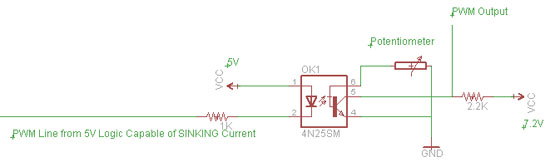
im building a project where basicly a 12v quad bike is a rx car. I wish to isolate the 12v engine from a 2s lipo which will run the 2.4ghz recive. I wish to use 4n25 optos to isolate both sides. Now the issue I have how do I get the pen from the rx to control a servo on the other side. Both sides will have a 5v 3amp Bec to run the correct voltage. The above pic is the closest i can find to what I have tried. But I still not think this is write. As I'm doesn't work.. Any help please


chris

  • Sign in to reply
  • Cancel

Top Replies

  • jc2048
    jc2048 over 9 years ago +1 suggested
    If I understand you correctly, you're just looking for isolation for the PWM signal. You are most of the way there. To get it working, don't bother with the potentiometer, just leave pin 6 unconnected…
Parents
  • jc2048
    0 jc2048 over 9 years ago

    If I understand you correctly, you're just looking for isolation for the PWM signal.


    You are most of the way there. To get it working, don't bother with the potentiometer, just leave pin 6 unconnected. [It's there to try and improve the speed at which the transistor turns off, but you've got to get the adjustment just right - too high a resistance and it won't make any difference to the speed, too low and the transistor won't turn on because the pot is stealing too charge from the base. Too make it work as intended, you'd probably have to up the LED current. A lot of optocouplers don't even bring the base out to the ouside world - in a commercial design, you don't want to be fiddling around with adjustments like this.]


    The PWM signal going in does need to swing up to the 5V. If it's a CMOS output from a processor or CMOS logic, it will be fine. [Just mentioning it because, if the high level only got to 3V say, the LED would always be partly on. The forward voltage of the LED is only 1.1V, so any input voltage below 3.9V will produce some light and start pulling the output down.]


    Here's how the calculations work in case you're interested [and particularly if you think you might want to experiment a bit].


    The 1K resistor gives an LED current of 3.9mA [Ohm's Law: (5V-1.1V)/1000ohms] when the PWM is low and the LED is on. The current transfer ratio is about 70% [from the datasheet - there's no normal value for an optocoupler, you just have to look at the datasheet for the particular device type], so that will result in 2.7mA at the collector of the transistor. The minimum collector resistor to pull all the way down to zero volts is then 1850 ohms [5V/0.0027A]. [Bear in mind that, as you go to higher and higher resistor values, you slow the positive-going edge of the PWM more and more, and it may start to have an impact on your control signal. So don't choose a silly value like 100k. That's because any capacitance on the output has to charge up through that resistor, and the higher the resistor value the longer it takes. So pick a value that's just a bit higher than the minimum.]

    The 2.2k resistor works if what you've labelled as 'PWM Output' doesn't present a significant load on the output. If it does, then the transistor won't necessarily be able to pull the output all the way down and you'd need to up the LED current to get more current at the collector.


    To test it, measure the voltage at PWM Output whilst you turn the LED on and off by touching the end of the LED resistor that normally goes to PWM Line to 0V on the input side. You'll soon see if the transistor switches and whether it can pull the output all the way down.

    • Cancel
    • Vote Up +1 Vote Down
    • Sign in to reply
    • Verify Answer
    • Reject Answer
    • Cancel
Reply
  • jc2048
    0 jc2048 over 9 years ago

    If I understand you correctly, you're just looking for isolation for the PWM signal.


    You are most of the way there. To get it working, don't bother with the potentiometer, just leave pin 6 unconnected. [It's there to try and improve the speed at which the transistor turns off, but you've got to get the adjustment just right - too high a resistance and it won't make any difference to the speed, too low and the transistor won't turn on because the pot is stealing too charge from the base. Too make it work as intended, you'd probably have to up the LED current. A lot of optocouplers don't even bring the base out to the ouside world - in a commercial design, you don't want to be fiddling around with adjustments like this.]


    The PWM signal going in does need to swing up to the 5V. If it's a CMOS output from a processor or CMOS logic, it will be fine. [Just mentioning it because, if the high level only got to 3V say, the LED would always be partly on. The forward voltage of the LED is only 1.1V, so any input voltage below 3.9V will produce some light and start pulling the output down.]


    Here's how the calculations work in case you're interested [and particularly if you think you might want to experiment a bit].


    The 1K resistor gives an LED current of 3.9mA [Ohm's Law: (5V-1.1V)/1000ohms] when the PWM is low and the LED is on. The current transfer ratio is about 70% [from the datasheet - there's no normal value for an optocoupler, you just have to look at the datasheet for the particular device type], so that will result in 2.7mA at the collector of the transistor. The minimum collector resistor to pull all the way down to zero volts is then 1850 ohms [5V/0.0027A]. [Bear in mind that, as you go to higher and higher resistor values, you slow the positive-going edge of the PWM more and more, and it may start to have an impact on your control signal. So don't choose a silly value like 100k. That's because any capacitance on the output has to charge up through that resistor, and the higher the resistor value the longer it takes. So pick a value that's just a bit higher than the minimum.]

    The 2.2k resistor works if what you've labelled as 'PWM Output' doesn't present a significant load on the output. If it does, then the transistor won't necessarily be able to pull the output all the way down and you'd need to up the LED current to get more current at the collector.


    To test it, measure the voltage at PWM Output whilst you turn the LED on and off by touching the end of the LED resistor that normally goes to PWM Line to 0V on the input side. You'll soon see if the transistor switches and whether it can pull the output all the way down.

    • Cancel
    • Vote Up +1 Vote Down
    • Sign in to reply
    • Verify Answer
    • Reject Answer
    • Cancel
Children
No Data
element14 Community

element14 is the first online community specifically for engineers. Connect with your peers and get expert answers to your questions.

  • Members
  • Learn
  • Technologies
  • Challenges & Projects
  • Products
  • Store
  • About Us
  • Feedback & Support
  • FAQs
  • Terms of Use
  • Privacy Policy
  • Legal and Copyright Notices
  • Sitemap
  • Cookies

An Avnet Company © 2025 Premier Farnell Limited. All Rights Reserved.

Premier Farnell Ltd, registered in England and Wales (no 00876412), registered office: Farnell House, Forge Lane, Leeds LS12 2NE.

ICP 备案号 10220084.

Follow element14

  • X
  • Facebook
  • linkedin
  • YouTube