element14 Community
element14 Community
    Register Log In
  • Site
  • Search
  • Log In Register
  • About Us
  • Community Hub
    Community Hub
    • What's New on element14
    • Feedback and Support
    • Benefits of Membership
    • Personal Blogs
    • Members Area
    • Achievement Levels
  • Learn
    Learn
    • Ask an Expert
    • eBooks
    • element14 presents
    • Learning Center
    • Tech Spotlight
    • STEM Academy
    • Webinars, Training and Events
    • Learning Groups
  • Technologies
    Technologies
    • 3D Printing
    • FPGA
    • Industrial Automation
    • Internet of Things
    • Power & Energy
    • Sensors
    • Technology Groups
  • Challenges & Projects
    Challenges & Projects
    • Design Challenges
    • element14 presents Projects
    • Project14
    • Arduino Projects
    • Raspberry Pi Projects
    • Project Groups
  • Products
    Products
    • Arduino
    • Avnet Boards Community
    • Dev Tools
    • Manufacturers
    • Multicomp Pro
    • Product Groups
    • Raspberry Pi
    • RoadTests & Reviews
  • Store
    Store
    • Visit Your Store
    • Choose another store...
      • Europe
      •  Austria (German)
      •  Belgium (Dutch, French)
      •  Bulgaria (Bulgarian)
      •  Czech Republic (Czech)
      •  Denmark (Danish)
      •  Estonia (Estonian)
      •  Finland (Finnish)
      •  France (French)
      •  Germany (German)
      •  Hungary (Hungarian)
      •  Ireland
      •  Israel
      •  Italy (Italian)
      •  Latvia (Latvian)
      •  
      •  Lithuania (Lithuanian)
      •  Netherlands (Dutch)
      •  Norway (Norwegian)
      •  Poland (Polish)
      •  Portugal (Portuguese)
      •  Romania (Romanian)
      •  Russia (Russian)
      •  Slovakia (Slovak)
      •  Slovenia (Slovenian)
      •  Spain (Spanish)
      •  Sweden (Swedish)
      •  Switzerland(German, French)
      •  Turkey (Turkish)
      •  United Kingdom
      • Asia Pacific
      •  Australia
      •  China
      •  Hong Kong
      •  India
      •  Korea (Korean)
      •  Malaysia
      •  New Zealand
      •  Philippines
      •  Singapore
      •  Taiwan
      •  Thailand (Thai)
      • Americas
      •  Brazil (Portuguese)
      •  Canada
      •  Mexico (Spanish)
      •  United States
      Can't find the country/region you're looking for? Visit our export site or find a local distributor.
  • Translate
  • Profile
  • Settings
Robotics
  • Technologies
  • More
Robotics
Forum Help on connecting 24v Motors
  • Blog
  • Forum
  • Documents
  • Quiz
  • Events
  • Polls
  • Members
  • Mentions
  • Sub-Groups
  • Tags
  • More
  • Cancel
  • New
Join Robotics to participate - click to join for free!
Actions
  • Share
  • More
  • Cancel
Forum Thread Details
  • Replies 19 replies
  • Subscribers 65 subscribers
  • Views 3071 views
  • Users 0 members are here
  • 12v_power_systems
  • motor_control
  • 12v-to-24v
Related

Help on connecting 24v Motors

vandia
vandia over 8 years ago

Hi, I'm using an Intel Edison on Arduino. It is currently powered by a 12v/10A power supply. I plan to put in batteries later.


I'm making a larger machine, and need some decent torque to run it. I had 2 motor scooters that I honestly found in the trash can a few years back. I took them out hoping to use them for parts when the time came (now). They use a proprietary charging port, running on 24v. It contained two 12v batteries, and the motors are labeled as rated 12v/100W.


I'm having some issues with getting it to run in general. I've connected my 12v/10A power supply to it with weak connections, and had it run, but somewhat weakly. I'm sure at least part is how old and rusted the chain is.... these things have been outside for probably about 2 years in the elements.


What I know I'm going to need help with / questions answered:

-I plan to use a DPDT relay to control the motors. Unless someone has a better option. Cheapest ideas? I'm connecting 2 motors, and using differential steering.

-Are there certain pins (let's say PWM) that may work better for controlling these relays?

-Since the motors are rated 100A, will I be able to just give it lower voltage at higher amperage, since I only need torque, not speed?

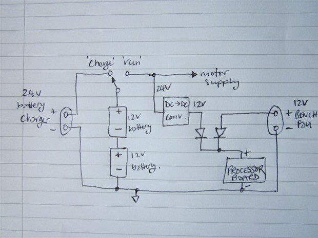
-How can I transform the 12v output from my batter(y/ies) to a 24v line to drive these motors? Series circuit would be out, because the Arduino will be running off that line.


Again, cost is one of my greatest concerns. But, weight is a secondary.


Bonus brownie points for if you can tell me what I can use for charging 12v batteries with my 12v/10A power supply with Type-M plug (5.5mm outer diameter, 2.1m inner), and how to tell if one of these batteries is bad or just dead that I ripped out of the scooter.

  • Sign in to reply
  • Cancel

Top Replies

  • jw0752
    jw0752 over 8 years ago +5
    Hi Vandia, The replies may be slow as we are scratching our heads a little to digest and analyse your questions and situation. Let me restate my understanding of your resources. You have two 100 Watt 12…
  • jw0752
    jw0752 over 8 years ago in reply to vandia +5
    If the motors are 24 volts and the charger input was 24 volts then the (2) 12 volt batteries were hooked in series. You can charge them with your 12 volts but they would have to be done individually or…
  • jc2048
    jc2048 over 8 years ago in reply to vandia +4
    Couple of thoughts to add to John's. You may know this anyway, but just in case not: 1. Safety A lead-acid battery can deliver a lot of current very, very quickly if you ask it to. By a lot of current…
  • Workshopshed
    Workshopshed over 8 years ago

    Is one of these any use?


    DC-MOTORCONTR_BTN8982 - Infineon Technologies

    • Cancel
    • Vote Up 0 Vote Down
    • Sign in to reply
    • Cancel
  • jw0752
    jw0752 over 8 years ago in reply to vandia

    Hi Vandia,


    How many Amps do you think it was taking at 12v then? Note, it did not just run slowly: The speed was actually "okay", it was the torque that I saw suffer.

    A motor that is not under load (doing work) can run with a relatively low current draw. As we demand more energy from the motor by impeding the rotation of the shaft that power has to come from somewhere. The impeding of the shaft rotation actually causes the impedance of the motor to drop which causes the current to increase. If our motor was operating without a load at 12 volts one amp ( 12 Watts ) impeding the shaft slightly might cause the current to increase to 2 amps. Our motor would now be consuming 24 watts from our power supply. Ideally 12 watts would still be used for internal losses in the motor and 12 watts would be consumed by whatever is impeding the shaft rotation. As we continue to increase the amount of resistance that we apply to the shaft rotation the current continues to climb. At some point we approach the limits of our power supply. You said that your power supply was 12 volt 10 amps (120 watts). As the motor's current draw approaches the 10 amp level your power supplies voltage level will drop. The internal resistance of your power supply will begin to be a critical factor in the equation. At some point your current to the motor might be 12 amps but the voltage that is being applied to the motor may have dropped to only 8 volts ( only 96 watts ). The other 4 volts is being applied to internal resistance in your power supply. This is why manufacturer's of power supplies rate them with a voltage and an amperage. It allow the designer to know the practical limits of the power that can be obtained.  Also note that at 12 volts to the motor we have to increase the current by 2 amps to get an additional 24 watts while at 24 volts we only have to increase the current by 1 amp to get the same 24 watt increase. This is why your motor seems to have poor torque at 12 volts and may not give you the power you require.


    John

    • Cancel
    • Vote Up +2 Vote Down
    • Sign in to reply
    • Cancel
  • vandia
    vandia over 8 years ago in reply to Workshopshed

    It is.... but I didn't see a price to buy it. I'd also have to probably buy parts from eBay or something, because my budget ATM. I'm still paying for renovations on my house, plus it would be good to know how to search what I'm looking for. Thanks! image

    • Cancel
    • Vote Up 0 Vote Down
    • Sign in to reply
    • Cancel
  • jc2048
    jc2048 over 8 years ago in reply to vandia

    It sounds like your best approach would be to buy a 24V charger rather than try to do it yourself - I would have thought you could get a Chinese replacement for the scooter charger for a reasonable price. That will do the charging with the proper voltages, but you'll need to make sure that the maximum current that the charger supplies is suitable for the batteries you've got; it doesn't matter if it's lower - the charging just takes longer - but you don't want it higher or the batteries will heat up too much. (Batteries heat up when they're charging because of the chemical reaction that's taking place. If you want to impress people, just say that they're 'exothermic'.) Do the batteries have an Ah rating marked on them? [Ah stands for Ampere-hour and is a measure of the electrical capacity - a 1Ah battery can supply 1A for one hour.]


    The commercial chargers will be designed to work with just the battery. I think it will mess up the change to trickle charging at the end if you steal current from the charging.

    • Cancel
    • Vote Up 0 Vote Down
    • Sign in to reply
    • Cancel
  • jc2048
    jc2048 over 8 years ago in reply to jc2048

    My first thought would be something like this (are you ok with circuit diagrams?). Others here may well have better ideas.


    image

    • Cancel
    • Vote Up +2 Vote Down
    • Sign in to reply
    • Cancel
  • vandia
    vandia over 8 years ago in reply to jc2048

    I don't have very much experience with schematics.... I presume to the right of the 12v converter are diodes?
    I don't know what the triangle at the bottom means, and what's the 12v on the right?


    Also, will these schematics allow the board to stay powered without interruption when being plugged in?


    Thanks for the effort in drawing this, btw! <3

    • Cancel
    • Vote Up +1 Vote Down
    • Sign in to reply
    • Cancel
  • rachaelp
    rachaelp over 8 years ago in reply to vandia

    vandia wrote:


    I presume to the right of the 12v converter are diodes?
    I don't know what the triangle at the bottom means, and what's the 12v on the right?


    Also, will these schematics allow the board to stay powered without interruption when being plugged in?Yes you are correct these are diodes.


    The triangle at the bottom is a GND symbol, and whilst it's not strictly necessary on this schematic as the whole return path is shown as it's all wired together, if there was another part than needed connecting to this then using that symbol there too would imply the connection.


    The 12V on the right appears to be an external 12V bench power supply. What Jon is doing with the two diodes is OR'ing the regulator output with a bench supply so you can plug in the bench supply to maintain a constant supply to your processor board before switching over to charge the batteries.


    Best Regards,


    Rachael

    • Cancel
    • Vote Up +1 Vote Down
    • Sign in to reply
    • Cancel
  • e14phil
    e14phil over 8 years ago in reply to vandia

    DCMOTORCONTRBTN8982TOBO1 INFINEON, DC Motor Control Shield | Farnell element14


    <3 from your friendly neighborhood e14 Farnell Staff.

    • Cancel
    • Vote Up 0 Vote Down
    • Sign in to reply
    • Cancel
  • jc2048
    jc2048 over 8 years ago in reply to vandia

    It isn't a finished circuit - it's just a quick sketch of a possible approach, an idea of how it might be done. I should have explained it better.


    The diodes allow a current to flow only in the direction of the arrow that makes up the body of the shape on the circuit. So current can flow from the DC-DC converter output, through the diode, and power the processor. Similarly, current could flow from your bench supply, through its diode, and power the processor. So there are two ways to power the processor, the DC-DC converter OR the bench supply. The nice thing about the diode arrangement is when you consider the path from the DC-DC converter to the bench supply. Because the arrows face each other, there's no path for the current and you won't get one trying to power the other. That means you can have both supplies there at the same time and the processor will be powered from whichever happens to have the higher voltage. So you could apply the bench PSU whilst the processor was powered from the batteries, switch the batteries over to the charger, and have the processor continue like nothing had happened. [It would be a bit of a clunky arrangement for a commercial product, but for a personal project, where you knew what it does and why, you might decide to go with the simplicity.]


    Just for future reference, diodes aren't perfect and have various difficiencies you need to take into account when designing. There is a small leakage current when a diode is in reverse, but it's very small and wouldn't worry us here. Another deficiency, that's slightly more of a nuisance, is that when the diode is conducting forward current there's a voltage drop across it. In this case, the voltage that the processor board sees will be less than 12V - I'm assuming that that doesn't matter and that the power circuit on the processor board will operate over a fairly wide range.


    Putting in the 0V reference is just force of habit. I suppose some of it is history - partly because I'm old enough to remember when a good proportion of cars (automobiles) and motorbikes had positive grounds and also because of the early days of germanium transistors when circuit diagrams often had a positive ground and a negative power rail.

    • Cancel
    • Vote Up +1 Vote Down
    • Sign in to reply
    • Cancel
<
element14 Community

element14 is the first online community specifically for engineers. Connect with your peers and get expert answers to your questions.

  • Members
  • Learn
  • Technologies
  • Challenges & Projects
  • Products
  • Store
  • About Us
  • Feedback & Support
  • FAQs
  • Terms of Use
  • Privacy Policy
  • Legal and Copyright Notices
  • Sitemap
  • Cookies

An Avnet Company © 2025 Premier Farnell Limited. All Rights Reserved.

Premier Farnell Ltd, registered in England and Wales (no 00876412), registered office: Farnell House, Forge Lane, Leeds LS12 2NE.

ICP 备案号 10220084.

Follow element14

  • X
  • Facebook
  • linkedin
  • YouTube