element14 Community
element14 Community
    Register Log In
  • Site
  • Search
  • Log In Register
  • Community Hub
    Community Hub
    • What's New on element14
    • Feedback and Support
    • Benefits of Membership
    • Personal Blogs
    • Members Area
    • Achievement Levels
  • Learn
    Learn
    • Ask an Expert
    • eBooks
    • element14 presents
    • Learning Center
    • Tech Spotlight
    • STEM Academy
    • Webinars, Training and Events
    • Learning Groups
  • Technologies
    Technologies
    • 3D Printing
    • FPGA
    • Industrial Automation
    • Internet of Things
    • Power & Energy
    • Sensors
    • Technology Groups
  • Challenges & Projects
    Challenges & Projects
    • Design Challenges
    • element14 presents Projects
    • Project14
    • Arduino Projects
    • Raspberry Pi Projects
    • Project Groups
  • Products
    Products
    • Arduino
    • Avnet Boards Community
    • Dev Tools
    • Manufacturers
    • Multicomp Pro
    • Product Groups
    • Raspberry Pi
    • RoadTests & Reviews
  • About Us
  • Store
    Store
    • Visit Your Store
    • Choose another store...
      • Europe
      •  Austria (German)
      •  Belgium (Dutch, French)
      •  Bulgaria (Bulgarian)
      •  Czech Republic (Czech)
      •  Denmark (Danish)
      •  Estonia (Estonian)
      •  Finland (Finnish)
      •  France (French)
      •  Germany (German)
      •  Hungary (Hungarian)
      •  Ireland
      •  Israel
      •  Italy (Italian)
      •  Latvia (Latvian)
      •  
      •  Lithuania (Lithuanian)
      •  Netherlands (Dutch)
      •  Norway (Norwegian)
      •  Poland (Polish)
      •  Portugal (Portuguese)
      •  Romania (Romanian)
      •  Russia (Russian)
      •  Slovakia (Slovak)
      •  Slovenia (Slovenian)
      •  Spain (Spanish)
      •  Sweden (Swedish)
      •  Switzerland(German, French)
      •  Turkey (Turkish)
      •  United Kingdom
      • Asia Pacific
      •  Australia
      •  China
      •  Hong Kong
      •  India
      •  Korea (Korean)
      •  Malaysia
      •  New Zealand
      •  Philippines
      •  Singapore
      •  Taiwan
      •  Thailand (Thai)
      • Americas
      •  Brazil (Portuguese)
      •  Canada
      •  Mexico (Spanish)
      •  United States
      Can't find the country/region you're looking for? Visit our export site or find a local distributor.
  • Translate
  • Profile
  • Settings
Sensors
  • Technologies
  • More
Sensors
Sensor Forum Trying to understand how R & C affect an audio signal when used in a high pass filter
  • Blog
  • Forum
  • Documents
  • Quiz
  • Events
  • Polls
  • Members
  • Mentions
  • Sub-Groups
  • Tags
  • More
  • Cancel
  • New
Join Sensors to participate - click to join for free!
Actions
  • Share
  • More
  • Cancel
Forum Thread Details
  • State Suggested Answer
  • Replies 41 replies
  • Answers 18 answers
  • Subscribers 343 subscribers
  • Views 7450 views
  • Users 0 members are here
  • high pass filter
Related

Trying to understand how R & C affect an audio signal when used in a high pass filter

BigG
BigG over 5 years ago

Hi all,


I am looking at creating a simple high pass filter for a microphone breakout board which will be attached to a MCU.


I'm not an electronics engineer so this is probably a simple 101 type question for those who are.


I've learnt from Wikipedia that the formula for determining the cut off frequency is:


image


and that R x C is the time constant.


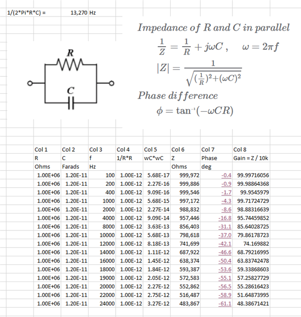
Now what I am trying to learn is how else does R and C impact the audio signal as this presents me with 2 degrees of freedom.


For example if I went with a 100 ohm resistor and say used a 1 uF capacitor, how does this compare with a 100k Ohm resistor and a 1 nF capacitor as both these options give me the same fc.


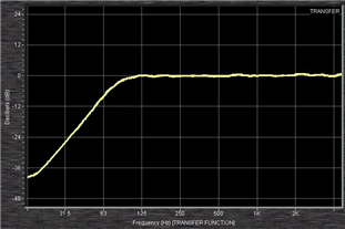
I'm assuming it must impact that ramp up curve but not sure how (image source Wikipedia).


image


Hence the question to the community experts.


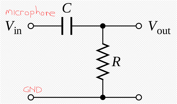
The circuit I'm using is as follows:


image

  • Sign in to reply
  • Cancel

Top Replies

  • michaelkellett
    michaelkellett over 5 years ago +5 suggested
    The formula is absolutely correct, the actual values of R and C don't matter in the context of the circuit you have drawn. The plot you have attached is not quite correct for the circuit you have drawn…
  • michaelkellett
    michaelkellett over 5 years ago in reply to shabaz +5 suggested
    The DC operating point doesn't look quite right in LTSpice: What do you see on Q1 collector in real life ? Reduce R4 to 1k2 and it's much nearer the mid point, and can manage 1.6V pk-pk with a bit of distortion…
  • jc2048
    jc2048 over 5 years ago in reply to shabaz +4
    This exchange was interesting. One observation: if you drop the value of the input capacitor to 1uF or less, you could also afford to drop the emitter capacitor in value too [would help a bit if it needs…
Parents
  • michaelkellett
    0 michaelkellett over 5 years ago

    The formula is absolutely correct, the actual values of R and C don't matter in the context of the circuit you have drawn.

    The plot you have attached is not quite correct for the circuit you have drawn (the very LF end of the trace is "turning up" which it should not do).


    In real life the source and load that are not shown in the circuit might have an additional effect.


    Try simulating with a source resistance equal to R and you'll see some difference, or add some parasitic capacitance to the load.


    Other things matter too, if the R is large the filter may cause noise, partly because of thermal noise in the resistor and partly because the amplifier after the filter may be quieter if driven from a low source impedance.


    For a microphone you might want fc to be 100Hz, a good value of capacitor, if you don't much care about noise, would be 100nF, which you can easily get in plastic film or ceramic surface mount at low cost. For audio with any pretensions to quality you should avoid ceramic capacitors because they are often microphonic. Your 100nF cap would need a 16k resistor. If you do care about noise then it gets a bit more complicated and you would need to know what kind of microphone and the design of the load circuits to make a choice.


    MK

    • Cancel
    • Vote Up +5 Vote Down
    • Sign in to reply
    • Verify Answer
    • Reject Answer
    • Cancel
Reply
  • michaelkellett
    0 michaelkellett over 5 years ago

    The formula is absolutely correct, the actual values of R and C don't matter in the context of the circuit you have drawn.

    The plot you have attached is not quite correct for the circuit you have drawn (the very LF end of the trace is "turning up" which it should not do).


    In real life the source and load that are not shown in the circuit might have an additional effect.


    Try simulating with a source resistance equal to R and you'll see some difference, or add some parasitic capacitance to the load.


    Other things matter too, if the R is large the filter may cause noise, partly because of thermal noise in the resistor and partly because the amplifier after the filter may be quieter if driven from a low source impedance.


    For a microphone you might want fc to be 100Hz, a good value of capacitor, if you don't much care about noise, would be 100nF, which you can easily get in plastic film or ceramic surface mount at low cost. For audio with any pretensions to quality you should avoid ceramic capacitors because they are often microphonic. Your 100nF cap would need a 16k resistor. If you do care about noise then it gets a bit more complicated and you would need to know what kind of microphone and the design of the load circuits to make a choice.


    MK

    • Cancel
    • Vote Up +5 Vote Down
    • Sign in to reply
    • Verify Answer
    • Reject Answer
    • Cancel
Children
  • BigG
    0 BigG over 5 years ago in reply to michaelkellett

    Thanks for insight.


    Maybe I should've also stated my intentions with the high pass filter as that may sway things.


    What I am hoping to do is only capture frequencies above 1.5kHz or even 3kHz and frequencies below that are ignored or significantly dampened,


    I had been toying with another acoustics project idea when I stumbled across this article: https://blog.medel.com/the-best-smoke-detector-for-hearing-loss/

    • Cancel
    • Vote Up +2 Vote Down
    • Sign in to reply
    • Verify Answer
    • Cancel
  • shabaz
    0 shabaz over 5 years ago in reply to michaelkellett

    I found these small Panasonic film caps when I was working on a project over xmas; I hadn't seen surface-mount film caps before!

    https://uk.farnell.com/w/c/passive-components/capacitors/film-capacitors/general-purpose-dc-film-capacitors?product-rang…

    • Cancel
    • Vote Up +1 Vote Down
    • Sign in to reply
    • Verify Answer
    • Cancel
  • michaelkellett
    0 michaelkellett over 5 years ago in reply to shabaz

    I'm a bit worried about using those except when re-flowed properly in a decent oven - but apart from that they are quite nice.

    They don't quote temperature coefficient.


    MK

    • Cancel
    • Vote Up +3 Vote Down
    • Sign in to reply
    • Verify Answer
    • Reject Answer
    • Cancel
  • michaelkellett
    0 michaelkellett over 5 years ago in reply to BigG

    If you plan to feed the microphone signal into a processor port you might need an amplifier but the smoke alarm may be loud enough that you don't.

    You could almost certainly get away with a passive filter between the processor and the microphone - if you can tell me which microphone you will use I could suggest a filter circuit.


    MK

    • Cancel
    • Vote Up +3 Vote Down
    • Sign in to reply
    • Verify Answer
    • Reject Answer
    • Cancel
  • shabaz
    0 shabaz over 5 years ago in reply to michaelkellett

    I wasn't too sure doing it manually either : ) Tried soldering them as quickly as I could..

    These are the 1uF parts in the photo below.

    image

    • Cancel
    • Vote Up +1 Vote Down
    • Sign in to reply
    • Verify Answer
    • Cancel
  • BigG
    0 BigG over 5 years ago in reply to michaelkellett

    I was planning to start by using an amplified mic breakout, as I have quite a few different ones. I was planning to place the high pass filter post amplification but before MCU input

    https://www.sparkfun.com/products/9868

    https://www.adafruit.com/product/1063

    https://www.freetronics.com.au/products/microphone-sound-input-module#.XmUb2ErLfIU


    I think I have some electrec and mems microphones lying around too in some box somewhere.


    Open to all suggestions.

    • Cancel
    • Vote Up +3 Vote Down
    • Sign in to reply
    • Verify Answer
    • Reject Answer
    • Cancel
  • michaelkellett
    0 michaelkellett over 5 years ago in reply to BigG

    The Freetronics module has a digital output or an analogue output. It has more gain than you will need and some filtering around the op amp. You could easily mod the board to give you the gain and frequency response you want.

    (Change C1 to 10nF to get 1.59 kHz lf cut off and reduce R4 to perhaps as low as 20k to get the gain down (you will need to check signals when listening to the Smoke Alarm)). You could change the capacitor across R4 to add some HF filtering.


    MK

    • Cancel
    • Vote Up +3 Vote Down
    • Sign in to reply
    • Verify Answer
    • Reject Answer
    • Cancel
  • BigG
    0 BigG over 5 years ago in reply to michaelkellett

    I'm rather pleased I decided to post this question as the freetronics mic option was not my first choice. Nice that these are 0603 components so can hand solder without too much difficulty.  So, thanks for your help.


    When you say "you could change the capacitor across R4 to add some HF filtering." are you referring to C2.

    • Cancel
    • Vote Up +1 Vote Down
    • Sign in to reply
    • Verify Answer
    • Cancel
  • michaelkellett
    0 michaelkellett over 5 years ago in reply to BigG

    Yes, C2 working with R4 sets a low pass cut off at 1/(2.pi.R4.C2) but only if R4 >> R3 (ie R4 >> 5 x R3).


    This implies that you can only use R4,C2 as the low pass filter if the amplifier is required to have some gain.


    I just checked, the amplifier on the Freetronics board does not have rail to rail output, which means that if you do the obvious and power it from 3.3V to work with a 3.3V micro then it won't work well.

    You could change the op amp for a true rail to rail input and output part, or use the Sparkfun board which costs a little more and has only analogue output but has a more suitable op amp fitted.


    MK

    • Cancel
    • Vote Up +3 Vote Down
    • Sign in to reply
    • Verify Answer
    • Reject Answer
    • Cancel
  • fmilburn
    0 fmilburn over 5 years ago in reply to michaelkellett

    Hi Michael


    I am trying to get an intuitive feel for what changing C2 in the Freetronics board does.  If there is no C2 then there is a straight forward inverting amplifier with gain of R4 / R2.  With C2 parallel to R4 in place then at higher frequencies the gain would intuitively be reduced because the negative feedback impedance of the op amp is reduced which reduces gain and thus it acts as a low pass filter.  Is that a valid way to think about it?


    Anyway, if the values on the Freetronics board are placed into the formula you give above then I get cut off at 13,200 Hz.  This seems low given human hearing and electret mics (maybe not cheap ones) can detect higher.


    Ignoring R2 for the moment I set up a spreadsheet and calculated the impedance for R4 and C2 in parallel and varied it with frequency.  Column 6 is the resultant total impedance and column 7 is the phase angle.  Then assume the total impedance in column 6 can be divided by R2 (10,000 ohm) to get the gain as given in column 8.  Varying the frequency in column 3 gives a 50% gain reduction at roughly 22 kHz by this method.  So my question is whether this is a proper calculation and also wouldn't the phase angle distort the sound?  It does not give sharp cut off either.  Is it a good idea to even have C2 in this application?


    image


    Finally, I don't understand what is being done with the sound pressure level output.  The notes on the schematic say that the pin voltage varies with sound pressure level.  But it looks like a comparator with a low pass filter following it.  The comparison voltage is set at roughly 0.07 V with a voltage divider.  The notes describe the low pass filter (I get 60.29 Hz cut off) as “sound level storage.”  I can see where it does something but it doesn't seem like it is meaningful sound pressure level which is normally given in decibels.


    Thanks for the thoughtful and knowledgeable answers you give.


    Frank

    • Cancel
    • Vote Up +2 Vote Down
    • Sign in to reply
    • Verify Answer
    • Reject Answer
    • Cancel
element14 Community

element14 is the first online community specifically for engineers. Connect with your peers and get expert answers to your questions.

  • Members
  • Learn
  • Technologies
  • Challenges & Projects
  • Products
  • Store
  • About Us
  • Feedback & Support
  • FAQs
  • Terms of Use
  • Privacy Policy
  • Legal and Copyright Notices
  • Sitemap
  • Cookies

An Avnet Company © 2025 Premier Farnell Limited. All Rights Reserved.

Premier Farnell Ltd, registered in England and Wales (no 00876412), registered office: Farnell House, Forge Lane, Leeds LS12 2NE.

ICP 备案号 10220084.

Follow element14

  • X
  • Facebook
  • linkedin
  • YouTube