element14 Community
element14 Community
    Register Log In
  • Site
  • Search
  • Log In Register
  • Community Hub
    Community Hub
    • What's New on element14
    • Feedback and Support
    • Benefits of Membership
    • Personal Blogs
    • Members Area
    • Achievement Levels
  • Learn
    Learn
    • Ask an Expert
    • eBooks
    • element14 presents
    • Learning Center
    • Tech Spotlight
    • STEM Academy
    • Webinars, Training and Events
    • Learning Groups
  • Technologies
    Technologies
    • 3D Printing
    • FPGA
    • Industrial Automation
    • Internet of Things
    • Power & Energy
    • Sensors
    • Technology Groups
  • Challenges & Projects
    Challenges & Projects
    • Design Challenges
    • element14 presents Projects
    • Project14
    • Arduino Projects
    • Raspberry Pi Projects
    • Project Groups
  • Products
    Products
    • Arduino
    • Avnet & Tria Boards Community
    • Dev Tools
    • Manufacturers
    • Multicomp Pro
    • Product Groups
    • Raspberry Pi
    • RoadTests & Reviews
  • About Us
  • Store
    Store
    • Visit Your Store
    • Choose another store...
      • Europe
      •  Austria (German)
      •  Belgium (Dutch, French)
      •  Bulgaria (Bulgarian)
      •  Czech Republic (Czech)
      •  Denmark (Danish)
      •  Estonia (Estonian)
      •  Finland (Finnish)
      •  France (French)
      •  Germany (German)
      •  Hungary (Hungarian)
      •  Ireland
      •  Israel
      •  Italy (Italian)
      •  Latvia (Latvian)
      •  
      •  Lithuania (Lithuanian)
      •  Netherlands (Dutch)
      •  Norway (Norwegian)
      •  Poland (Polish)
      •  Portugal (Portuguese)
      •  Romania (Romanian)
      •  Russia (Russian)
      •  Slovakia (Slovak)
      •  Slovenia (Slovenian)
      •  Spain (Spanish)
      •  Sweden (Swedish)
      •  Switzerland(German, French)
      •  Turkey (Turkish)
      •  United Kingdom
      • Asia Pacific
      •  Australia
      •  China
      •  Hong Kong
      •  India
      •  Korea (Korean)
      •  Malaysia
      •  New Zealand
      •  Philippines
      •  Singapore
      •  Taiwan
      •  Thailand (Thai)
      • Americas
      •  Brazil (Portuguese)
      •  Canada
      •  Mexico (Spanish)
      •  United States
      Can't find the country/region you're looking for? Visit our export site or find a local distributor.
  • Translate
  • Profile
  • Settings
Sensors
  • Technologies
  • More
Sensors
Sensor Forum Photocell/Photoresistor Light Resistance
  • Blog
  • Forum
  • Documents
  • Quiz
  • Events
  • Polls
  • Members
  • Mentions
  • Sub-Groups
  • Tags
  • More
  • Cancel
  • New
Join Sensors to participate - click to join for free!
Actions
  • Share
  • More
  • Cancel
Forum Thread Details
  • State Suggested Answer
  • Replies 1 reply
  • Answers 1 answer
  • Subscribers 342 subscribers
  • Views 416 views
  • Users 0 members are here
Related

Photocell/Photoresistor Light Resistance

Former Member
Former Member over 12 years ago

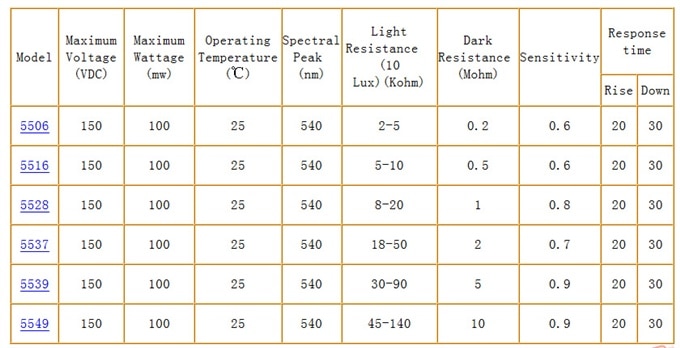
I am new to electronics.  I am looking at purchasing a photocell (photoresistor) for some of my projects.  I have observed that there are different levels of light resistance for different photocells -- see "Light Resistance" Column below.  What is the significance of the different Light Resistance levels?  Same basic question for "Dark Resistance" column and "Sensitivity" column.  I'm just trying to determine which model of photoresistor to purchase for my needs.  Thanks for your input!


https://community.element14.com/resized-image/__size/1200x900/__key/communityserver-discussions-components-files/17/contentimage_5F00_26717.html

image

  • Sign in to reply
  • Cancel

Top Replies

  • ChuckMcM
    ChuckMcM over 12 years ago +1 suggested
    "Dark Resistance" is the resistance your photocell will have when it is completely dark, "Light Resistance" describes how much the resistance will change based on the amount of light that lands on the…
Parents
  • ChuckMcM
    0 ChuckMcM over 12 years ago

    "Dark Resistance" is the resistance your photocell will have when it is completely dark, "Light Resistance" describes how much the resistance will change based on the amount of light that lands on the photocell, and "Response Time" is how long it will take for the final reading to be reached.


    So lets start with things that are common to all of them, they are all rated at up to 150volts DC (You probably won't get close to that) they are also all rated for a maximum power dissipation of 100mW. Since power in a resistor is equal ti the current squared * the resistance, you want to be sure that when the device has its lowest resistance you are not putting too much current through it. Generally that isn't a problem either since with a reasonably low voltage (say 5V) you will be hard pressed to push more than a few microamps through the cell (5V/500000 ohms when dark = 10nA, or 50nW). Their resistance is measured at 25 degrees C so if you're going to be running hotter or colder than that and you want to measure small variations in light you may want to check for the change over temperature. They are all peaking at 540nm which is Greenish/Yellowish light (you'd think it was green).


    So lets say you wanted to use the first one on the list. If you hooked it up 5V -> photocell -> * -> 200K resistor -> Ground. And then measured the voltage between the * and ground. When it was dark, the Cell would have a resistance of 200K ohms, and the lower resistor would be 200K ohms, and in classic voltage divider fashion the voltage drop across the lower 200K resistor would be 2.5V (5V - 5V * R1/(R1+R2)) [1]. But if you had 10 lux of light shining on it, the Cell resistance would go up by 5K ohms, so the new voltage would be 5 - 5 * (205/405) or 2.47V. If you were reading that on a microprocessor with a ADC you would see the voltage go down slightly.


    More typically you might put the photocell divider to an op-amp, put 2.5V into the positive side, your divider into the positive side, and then build a feedback circuit (a resistor between the output and the voltage divider) that would adjust your gain. Then you could create a voltage from 0 to Vmax (what ever the OpAmp's power rail was). That is useful if you want to measure the light incident to the photocell.


    Lastly you might put the photocell input into a comparator and use that to change state when a certain level of light had been reached.


    It really depends on what your final application is.


    --Chuck

    • Cancel
    • Vote Up +1 Vote Down
    • Sign in to reply
    • Verify Answer
    • Reject Answer
    • Cancel
Reply
  • ChuckMcM
    0 ChuckMcM over 12 years ago

    "Dark Resistance" is the resistance your photocell will have when it is completely dark, "Light Resistance" describes how much the resistance will change based on the amount of light that lands on the photocell, and "Response Time" is how long it will take for the final reading to be reached.


    So lets start with things that are common to all of them, they are all rated at up to 150volts DC (You probably won't get close to that) they are also all rated for a maximum power dissipation of 100mW. Since power in a resistor is equal ti the current squared * the resistance, you want to be sure that when the device has its lowest resistance you are not putting too much current through it. Generally that isn't a problem either since with a reasonably low voltage (say 5V) you will be hard pressed to push more than a few microamps through the cell (5V/500000 ohms when dark = 10nA, or 50nW). Their resistance is measured at 25 degrees C so if you're going to be running hotter or colder than that and you want to measure small variations in light you may want to check for the change over temperature. They are all peaking at 540nm which is Greenish/Yellowish light (you'd think it was green).


    So lets say you wanted to use the first one on the list. If you hooked it up 5V -> photocell -> * -> 200K resistor -> Ground. And then measured the voltage between the * and ground. When it was dark, the Cell would have a resistance of 200K ohms, and the lower resistor would be 200K ohms, and in classic voltage divider fashion the voltage drop across the lower 200K resistor would be 2.5V (5V - 5V * R1/(R1+R2)) [1]. But if you had 10 lux of light shining on it, the Cell resistance would go up by 5K ohms, so the new voltage would be 5 - 5 * (205/405) or 2.47V. If you were reading that on a microprocessor with a ADC you would see the voltage go down slightly.


    More typically you might put the photocell divider to an op-amp, put 2.5V into the positive side, your divider into the positive side, and then build a feedback circuit (a resistor between the output and the voltage divider) that would adjust your gain. Then you could create a voltage from 0 to Vmax (what ever the OpAmp's power rail was). That is useful if you want to measure the light incident to the photocell.


    Lastly you might put the photocell input into a comparator and use that to change state when a certain level of light had been reached.


    It really depends on what your final application is.


    --Chuck

    • Cancel
    • Vote Up +1 Vote Down
    • Sign in to reply
    • Verify Answer
    • Reject Answer
    • Cancel
Children
No Data
element14 Community

element14 is the first online community specifically for engineers. Connect with your peers and get expert answers to your questions.

  • Members
  • Learn
  • Technologies
  • Challenges & Projects
  • Products
  • Store
  • About Us
  • Feedback & Support
  • FAQs
  • Terms of Use
  • Privacy Policy
  • Legal and Copyright Notices
  • Sitemap
  • Cookies

An Avnet Company © 2025 Premier Farnell Limited. All Rights Reserved.

Premier Farnell Ltd, registered in England and Wales (no 00876412), registered office: Farnell House, Forge Lane, Leeds LS12 2NE.

ICP 备案号 10220084.

Follow element14

  • X
  • Facebook
  • linkedin
  • YouTube