element14 Community
element14 Community
    Register Log In
  • Site
  • Search
  • Log In Register
  • Community Hub
    Community Hub
    • What's New on element14
    • Feedback and Support
    • Benefits of Membership
    • Personal Blogs
    • Members Area
    • Achievement Levels
  • Learn
    Learn
    • Ask an Expert
    • eBooks
    • element14 presents
    • Learning Center
    • Tech Spotlight
    • STEM Academy
    • Webinars, Training and Events
    • Learning Groups
  • Technologies
    Technologies
    • 3D Printing
    • FPGA
    • Industrial Automation
    • Internet of Things
    • Power & Energy
    • Sensors
    • Technology Groups
  • Challenges & Projects
    Challenges & Projects
    • Design Challenges
    • element14 presents Projects
    • Project14
    • Arduino Projects
    • Raspberry Pi Projects
    • Project Groups
  • Products
    Products
    • Arduino
    • Avnet Boards Community
    • Dev Tools
    • Manufacturers
    • Multicomp Pro
    • Product Groups
    • Raspberry Pi
    • RoadTests & Reviews
  • About Us
  • Store
    Store
    • Visit Your Store
    • Choose another store...
      • Europe
      •  Austria (German)
      •  Belgium (Dutch, French)
      •  Bulgaria (Bulgarian)
      •  Czech Republic (Czech)
      •  Denmark (Danish)
      •  Estonia (Estonian)
      •  Finland (Finnish)
      •  France (French)
      •  Germany (German)
      •  Hungary (Hungarian)
      •  Ireland
      •  Israel
      •  Italy (Italian)
      •  Latvia (Latvian)
      •  
      •  Lithuania (Lithuanian)
      •  Netherlands (Dutch)
      •  Norway (Norwegian)
      •  Poland (Polish)
      •  Portugal (Portuguese)
      •  Romania (Romanian)
      •  Russia (Russian)
      •  Slovakia (Slovak)
      •  Slovenia (Slovenian)
      •  Spain (Spanish)
      •  Sweden (Swedish)
      •  Switzerland(German, French)
      •  Turkey (Turkish)
      •  United Kingdom
      • Asia Pacific
      •  Australia
      •  China
      •  Hong Kong
      •  India
      •  Korea (Korean)
      •  Malaysia
      •  New Zealand
      •  Philippines
      •  Singapore
      •  Taiwan
      •  Thailand (Thai)
      • Americas
      •  Brazil (Portuguese)
      •  Canada
      •  Mexico (Spanish)
      •  United States
      Can't find the country/region you're looking for? Visit our export site or find a local distributor.
  • Translate
  • Profile
  • Settings
Sensors
  • Technologies
  • More
Sensors
Sensor Forum Understanding the differences between Gyroscopes and Accelerometers
  • Blog
  • Forum
  • Documents
  • Quiz
  • Events
  • Polls
  • Members
  • Mentions
  • Sub-Groups
  • Tags
  • More
  • Cancel
  • New
Join Sensors to participate - click to join for free!
Actions
  • Share
  • More
  • Cancel
Forum Thread Details
  • State Suggested Answer
  • Replies 21 replies
  • Answers 5 answers
  • Subscribers 345 subscribers
  • Views 4378 views
  • Users 0 members are here
Related

Understanding the differences between Gyroscopes and Accelerometers

Former Member
Former Member over 10 years ago

Hello all,

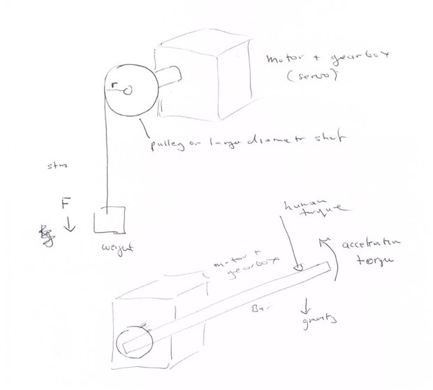
I apologize for what is likely an ignorant question, but I am fairly new to electronics and have little confidence. I am working on a personal project where I am using a servo motor to move a rod back forth 90 degrees (not exactly, but this analogy should suffice), and I am interested in measuring the instantaneous (angular?) acceleration (I want to use it to calculate torque). Surprisingly, I have come across trouble while researching online for a sensor to do this. My understanding now is that an accelerometer is only capable of measuring linear acceleration (which means the object can't be rotating, right?), while a gyroscope only measures angular velocity when an object is spinning about an axis. Technically, the rod in my project isn't spinning-it's just rotating back and forth between two angles (0 and 90) on the XY plane. Is there a simply way/sensor to do this? More broadly, am I completely misunderstanding the uses of gyroscopes and accelerometers? I hope i explained the issue properly...

  • Sign in to reply
  • Cancel

Top Replies

  • amgalbu
    amgalbu over 10 years ago in reply to Former Member +1
    Accelerometer measure acceleration. According to physics , acceleration is a variation in speed. If an object is falling, its speed increases of 9.8 m/s every second, so its acceleration is 9.8 m/s^2 usually…
Parents
  • amgalbu
    0 amgalbu over 10 years ago

    I think you can get the same result using a cheap 3 axis accelerometerc mounted at the tip of the rod. You can measure the centripedal and tangential components of the acceleration to determine the current position of the rod, and from then infer the speed and angular acceleration

    • Cancel
    • Vote Up 0 Vote Down
    • Sign in to reply
    • Verify Answer
    • Cancel
  • vsluiter
    0 vsluiter over 10 years ago in reply to amgalbu

    Ambrogio Galbusera wrote:


    I think you can get the same result using a cheap 3 axis accelerometerc mounted at the tip of the rod. You can measure the centripedal and tangential components of the acceleration to determine the current position of the rod, and from then infer the speed and angular acceleration

    you would have to callibrate / compensate / align to not be affected by gravitational force (also measured as acceleration) and the signal you want to measure. Rotating in the horizontal plane could help.


    I don't understand madgorillaz '  concern about an accelerometer not being able to measure angular acceleration. If you mount an accelerometer on a disc which you'll start spinning, you will see the acceleration. Just be careful to align the sensitive axis to the direction of rotation, or take a 2D-sensor.


    You could also start hitting nails with heads and just buy an Invensense MPU6050 or ST LSM330DLC to have both gyroscope and accelerometer in one package. You can buy breakout boards for these at Sparkfun / ebay. Arduino libraries are available for the MPU6050, so you could start logging to your PC immediately. The MPU6050 has way better specs than the ST (Invensense: 16-bit ADC, 1000Hz data rate).

    • Cancel
    • Vote Up 0 Vote Down
    • Sign in to reply
    • Verify Answer
    • Cancel
  • Former Member
    0 Former Member over 10 years ago in reply to vsluiter

    Well I think I'm just having trouble understanding them. If an accelerometer can only measure acceleration from one axis at a time, how can it measure acceleration when it is mounted on an object that is rotating (not spinning)? Am I missing something fundamental?

    • Cancel
    • Vote Up 0 Vote Down
    • Sign in to reply
    • Verify Answer
    • Cancel
  • amgalbu
    0 amgalbu over 10 years ago in reply to Former Member

    It measures centrifugal (or centripedal) acceleration

    • Cancel
    • Vote Up 0 Vote Down
    • Sign in to reply
    • Verify Answer
    • Cancel
  • michaelkellett
    0 michaelkellett over 10 years ago in reply to amgalbu

    @John, The problem with estimating position by measuring acceleration is that you must integrate twice, which causes errors to increase with time.


    While it is, in theory, possible to estimate acceleration in any direction with a tri-axial accelerometer combined with a tri-axial gyro it works rather badly in practice when you are using low cost devices. Firstly you need to integrate the output of the gyros (since low cost parts will be rate gyros)  and then you must combine this information with the data from the accelerometers. In practice the estimate of acceleration is built on a complex calculation based on the output of six different sensors and  a lot of maths. The problem is compounded by the fact that gyros and accelerometers respond to off axis affects which also degrade accuracy. It can be done but it's not easy.

    If you have  a pot then use it - nice simple analogue signal which will go straight into your Arduino with no bother. A pot won't be as linear as an encoder but this may not matter. Because it's an analogue signal you can consider using analogue differentiation to convert the signal to acceleration (but try it in maths first).

    What will you use the acceleration signal for ?


    MK

    • Cancel
    • Vote Up 0 Vote Down
    • Sign in to reply
    • Verify Answer
    • Cancel
  • Former Member
    0 Former Member over 10 years ago in reply to michaelkellett

    Michael,

    The servo I am using actually has a built-in potentiometer which I now have access to. So the potentiometer should give me the position.

    I am using the servo to move a mounted rod back and forth (I'm currently moving it from 0 to 90 degrees-but the angle will change every time). What I am interested in is finding a way to calculate the instantaneous torque of the rod (or servo, I guess). While the rod is moving, there are times at which a force acting against the motion of the rod is applied, which is why the torque won't remain the same between each experiment (its actually going to be a person pushing against it-each time with differing levels of force). I am using a powerful, 200 oz.in servo with a 3:1 gear ratio, which means that the servo should push through most forces acting against it while moving at the same speed. The idea I had to calculate the torque was to place an accelerometer on the rod, and then use the values measured and multiply them by the moment of inertia. Theoretically, this should give me the torque, I was thinking. However, I'm not sure how accurate an accelerometer would be in this case, how to implement it, or if there are better ways to do what I want to do at a reasonable budget.

    • Cancel
    • Vote Up 0 Vote Down
    • Sign in to reply
    • Verify Answer
    • Cancel
  • michaelkellett
    0 michaelkellett over 10 years ago in reply to Former Member

    If you want to know torque then a really good rule is to measure it as directly as possible - if the rod speed is largely independent of the human load but it's the human load you want to measure then trying to estimate it by acceleration will be really inaccurate.

    The simplest way to measure torque is to measure the motor current but this may not be very accurate due to losses in the gearbox etc.

    If the rod is accelerating sufficiently fast that the acceleration torque is comparable with the human torque you can calculate the amount of torque needed to accelerate the rod and subtract it.

    You could make or buy a torque sensor.

    You could use  a low cost load cell to measure the force the human applies so long as you can arrange for that force to applied via the load cell. This will be the cheapest and most accurate way.


    What's your budget for the sensors ?


    MK

    • Cancel
    • Vote Up 0 Vote Down
    • Sign in to reply
    • Verify Answer
    • Reject Answer
    • Cancel
  • Former Member
    0 Former Member over 10 years ago in reply to michaelkellett

    It's not exactly a huge budget, unfortunately. I can't spend more than $100-200 on figuring out a way to measure torque in my final system. That number can go up if necessary (up to $400) but I'd rather keep it in the original range.

    For the load cell, I can't arrange it so that the force is always applied onto the sensor like you say. That's why I was thinking of looking at the rod. I'm sure there's a clever way to use a load cell but I'm unable to think of any ideas.

    I'm not sure what you're getting at with subtracting the acceleration of the rod? Is this basically how you propose I use an accelerometer?

    A torque sensor would be great but they seem to be very expensive. All of them seem to be over $1000. I have no idea how to make a torque sensor, do you? Is it accurate/inexpensive?

    I have thought about using the current as well. However, the servo is controlled using PWM. I bought a current sensor (it was really cheap), and the current I'm reading is like a square wave. So I'm not sure how to quantify this. Most importantly, I have no idea how I'd calibrate it.

    I'm sure what I'm trying to do is possible but I simply lack knowledge in this field. However, I do appreciate you helping me as much as you already have. That's really amazing of you.

    • Cancel
    • Vote Up 0 Vote Down
    • Sign in to reply
    • Verify Answer
    • Cancel
  • michaelkellett
    0 michaelkellett over 10 years ago in reply to Former Member

    You can buy little load cells quite cheaply (they are designed for weighing scales and might https://www.sparkfun.com/products/10245 - this isn't really sensitive enough for your purposes. In order to use two of these you would need to be able to machine metal parts (or get that done for you) .

    There are loads of cheap torque sensors made for automotive power steering but of course they are not documented for one off use and are hard to get except as spares.

    If you can glue strain gauges to a metal shaft you can make your own torque sensor but you don't want to try this unless you have or can borrow some experience in bonding gauges.


    If we stick with your motor current then all you need to do is to average the pulse width modulated signal  - if you can sample fast enough you can do this digitally. Calibration is easy - wind a string (thin) round the rotor of your servo + gearbox (possibly adding something to increase the diameter.) Hang a weight off the string and hold the weight still against gravity with the servo - you know the force and the diameter of the shaft so the torque is easy to calculate. It all gets much harder with dynamic systems because the inertial forces must be estimated or measure - in your system just make the rod light and ignore it. Using the motor current is so cheap I suggest you try it first and see how you get on.


    What sort of current sensor did you get ?


    MK

    • Cancel
    • Vote Up 0 Vote Down
    • Sign in to reply
    • Verify Answer
    • Reject Answer
    • Cancel
Reply
  • michaelkellett
    0 michaelkellett over 10 years ago in reply to Former Member

    You can buy little load cells quite cheaply (they are designed for weighing scales and might https://www.sparkfun.com/products/10245 - this isn't really sensitive enough for your purposes. In order to use two of these you would need to be able to machine metal parts (or get that done for you) .

    There are loads of cheap torque sensors made for automotive power steering but of course they are not documented for one off use and are hard to get except as spares.

    If you can glue strain gauges to a metal shaft you can make your own torque sensor but you don't want to try this unless you have or can borrow some experience in bonding gauges.


    If we stick with your motor current then all you need to do is to average the pulse width modulated signal  - if you can sample fast enough you can do this digitally. Calibration is easy - wind a string (thin) round the rotor of your servo + gearbox (possibly adding something to increase the diameter.) Hang a weight off the string and hold the weight still against gravity with the servo - you know the force and the diameter of the shaft so the torque is easy to calculate. It all gets much harder with dynamic systems because the inertial forces must be estimated or measure - in your system just make the rod light and ignore it. Using the motor current is so cheap I suggest you try it first and see how you get on.


    What sort of current sensor did you get ?


    MK

    • Cancel
    • Vote Up 0 Vote Down
    • Sign in to reply
    • Verify Answer
    • Reject Answer
    • Cancel
Children
  • Former Member
    0 Former Member over 10 years ago in reply to michaelkellett

    Well, let's assume I do buy 2 of those load cells. What exactly do I need to machine? Moreover, how should I integrate them? They seem very cheap and if they are as accurate as you say they are I'd like to buy them and try it.

    It seems like torque sensors and strain gauges won't be options at this point-thanks for letting me know. But do you really advise I avoid using an accelerometer? I was hoping it would be as easy as saying torque=moment of inertia * angular acceleration. That's why I originally wanted an accelerometer. But I definitely need accuracy too.

    I think I sort of understand what you're saying about calibrating the current, but I'm a little confused where you want me to tie the string. Should I tie it to the shaft of the large gear (I have a 3:1 gear ratio)? Or should I remove the servo itself from the gearbox? Here's a picture of a servo that looks similar to mine (the specs are not the same): ServoCity 2:1 Continuous Rotation Servo Power Gearbox - RobotShop

    Also, when you say "hold the weight still against gravity", do you mean I should hold the weight down while the servo is trying to move it up? Just want to make sure.

    Lastly, when you say ignore the rod, are you saying to include a rod during calibration? Or in my actual system? Because I think the rod in my system (i.e., while its rotating) has significant mass unfortunately.

    I'm currently using this sensor: http://www.adafruit.com/product/1164. Its an analog dc current sensor. However, I told you something incorrect before. I'm actually not sure if I'm currently able to sample fast enough to read the pulses that I should be getting from the servo. Is there a more appropriate sensor here? Or something else I can include in my circuit?

    • Cancel
    • Vote Up 0 Vote Down
    • Sign in to reply
    • Verify Answer
    • Cancel
  • D_Hersey
    0 D_Hersey over 10 years ago in reply to Former Member

    https://www.google.com/search?q=load%20cell%20site%3Aanalog.com&ie=utf-8&oe=utf-8&oq=load%20cell&gs_l=navquery.3...4641.…

    • Cancel
    • Vote Up 0 Vote Down
    • Sign in to reply
    • Verify Answer
    • Cancel
  • michaelkellett
    0 michaelkellett over 10 years ago in reply to D_Hersey

    @ John,


    torque=moment of inertia * angular acceleration, true, but only applies to the torque needed to move the bar, tells you nothing about the torque applied by the human.


    If the bar has significant mass you will need to measure the torque applied by the motor, subtract the bar acceleration torque and possibly subtract the torque due to  gravity acting on the mass of the bar.


    I've attached a pair of drawings produced on a special high tech mechanical simulation package. The top sketch shows the calibration setup. The lower sketch shows what I think your set up looks like (how about some photos from you - it would help).


    Remove the rod to calibrate, the servo should be holding the weight still so the force of the servo is balanced against the force of gravity acting on the weight.


    If the pulses from the current sensor are too fast then integrate them with a filter (anything from an RC to something active and exciting but without numbers I can't advise).


    image


    MK


    • Cancel
    • Vote Up 0 Vote Down
    • Sign in to reply
    • Verify Answer
    • Reject Answer
    • Cancel
element14 Community

element14 is the first online community specifically for engineers. Connect with your peers and get expert answers to your questions.

  • Members
  • Learn
  • Technologies
  • Challenges & Projects
  • Products
  • Store
  • About Us
  • Feedback & Support
  • FAQs
  • Terms of Use
  • Privacy Policy
  • Legal and Copyright Notices
  • Sitemap
  • Cookies

An Avnet Company © 2025 Premier Farnell Limited. All Rights Reserved.

Premier Farnell Ltd, registered in England and Wales (no 00876412), registered office: Farnell House, Forge Lane, Leeds LS12 2NE.

ICP 备案号 10220084.

Follow element14

  • X
  • Facebook
  • linkedin
  • YouTube