I've been playing with Cellular IoT this year.
I did a project with the Nordic Thingy:91 back in May - Thingy91 Dog Tracker to use GPS to record walks with my granddog.

And even earlier in the year I wrote a post when I started using a cellular kit from Blues Wireless - Blues Wireless Notecard.

Unfortunately, as often happens, I got busy with life and never got to using the hardware in a project. I'm hoping that I'll have time to do a few Cellular IoT projects with the Blues Notecards in the new year.
The typical application uses the Notecard as strictly a bidirectional cellular modem as shown in this clip from the documentation:
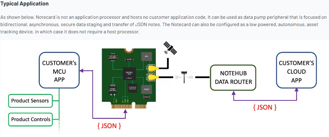
I'm also interested in the standalone asset tracking use case. This case is covered by the "card Requests" section of the Notecard API. The usage is described in detail in the Advanced Notecard Configuration documentation. That's what I'm going to be looking at, starting with this post.
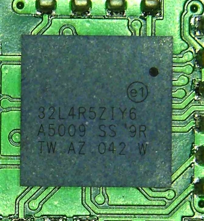
The Notecard SOM has a very capable STM32 ARM Cortex-M4F MCU with 2 Mbyte Flash. I wasn't sure which particular part was being used, so I looked at it using a USB microscope.
The Notecard is not user programmable, so you are limited to the functionality exposed by the API.
For this post I'm going to look at the GPIO functions and the BME280 sensor interface.
Since I'm just interested in the "card Requests" interface for this post, I'm going to use a WiFi Notecard rather than a cellular one. Besides the difference in communication, the only other major difference is that the WiFi version does not have the GNSS functionality which is part of the cellular module.
And I just a bought Sparkfun QWIIC Cellular Notecarrier, so I'm going to use that instead of a Blues Notecarrier (the Sparkfun board is supported by the Blues documentation).
Here is a picture of the Notecard on the Notecarrier.
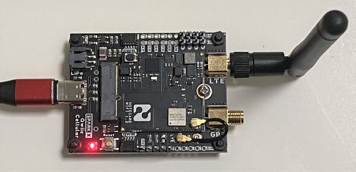


For this post I'm going to be working with the Notecard AUX pins. There are seven AUX pins that are brought out through the M2 edge connector. On the QWIIC Cellular Notecarrier these are brought out to pads near the LTE SMA antenna connector.
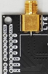
AUX1 - AUX4 are the 4 GPIO pins. Their function changes based on the AUX mode.
AUX EN/RX/TX provide a debug port that is separate from the primary Notecard communications (I2C/UART). These pins are dedicated and do not need to be configured.
I am going to focus on the GPIO pins.
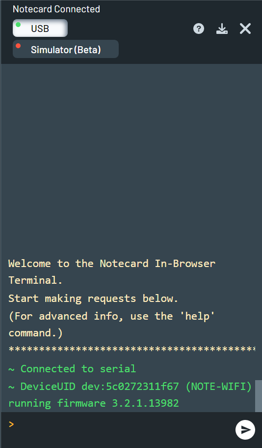
I covered the basic Notecard/Notecarrier setup in my previous post, so I won't repeat it here. I am going to use the same browser based terminal (using the Notecarrier USB port) to do the test configurations using JSON requests.
Here is the terminal view when I started:
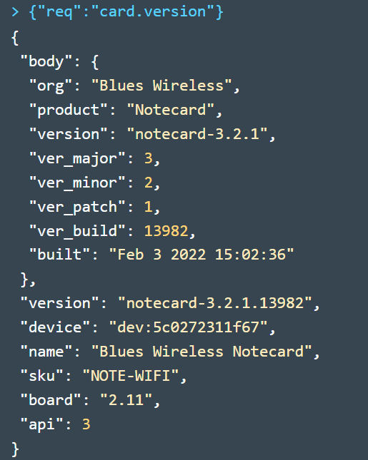
You can get detailed configuration info using the "card.version" query:
The next step was to configure WiFi by providing the request {"req":"card.wifi","ssid":"<ssid name>","password":"<password>"}.
Here is the response:

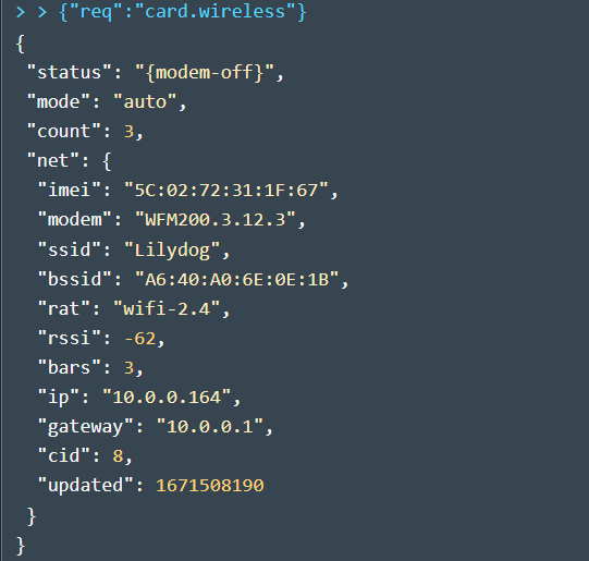
And a detailed configuration with the assigned ipaddr: (the WiFi Notecard only operates on 2.4 GHz)
Then I needed to associate the Notecard with a Notehub Product (needs to be preconfigured on the Notehub Dashboard):

Requires a manual sync to upload the request:
![]()
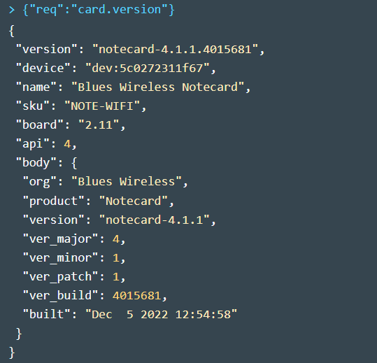
I decided to do a firmware update (DFU). This is simple to do after the device is connected to the Notehub. On the devices page - just need to select the Notecard Firmware tab and select the latest version to download. Took a while since it was updating over WiFi. I should time it when I do a cellular DFU.

Reconnect the USB Serial and verify the update.
Using GPIO Mode
Resync with the Notehub and ready to try out the GPIO.
First check the current AUX mode:
![]()
Then set it to GPIO mode:
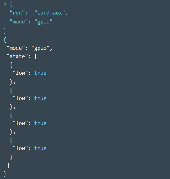
The GPIO pins are configurable to the following states via the usage argument:
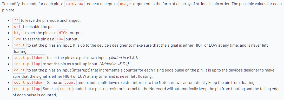
So, I tried the first example from the documentation - and it failed!
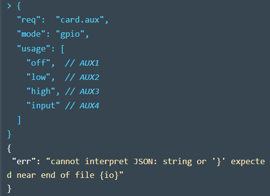
After some head-scratching I realized that it was because the example had comments in the JSON which are not allowed.
Removing the comments fixed it:
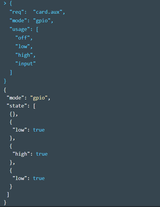
I verified the output states with a DMM and tried setting various other combinations successfully. I also verified on the Blues forum that the example was in error.
Using Monitor Mode
The Notecard has a test mode that allows the monitoring of notecard status both locally using LEDs and remotely by sending a note (_button.qo) to the Notehub.
There are two monitor modes:
- Use discrete LEDs on AUX2-4 to display status
- Use 1,2,or 5 Neopixel LEDs on AUX2
- Both modes use AUX1 as a test button to initiate sending a status note to the Notehub
I am going to test the Neopixel mode with a single Neopixel.
Here is the mode description:

Enable neo-monitor with single Neopixel:
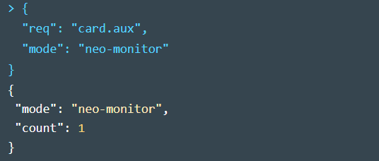
A demo of the Neopixel operation. I'm simulating a button press by grounding the AUX1 pin to initiate sending the _button.qo file. The initial "yellow" color looks a bit "red".
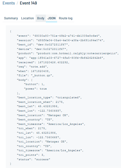
After the send sequence completes without error, the Event and the _button.qo file can be seen on Notehub.

And looking at the JSON we can see that the _button.qo file in addition to the location data has been received. I need to understand WiFi Triangulation better, but it is an experimental feature that is using the access point to ascertain a location.
Using BME280
I ran into a snag using the BME 280 with the WiFi Notecard. This configuration requires using the AUX Track Mode which might be disabled in the firmware because there no GNSS module which means there is no tracking capability (although there is apparently WiFi Triangulation)..
Here is the AUX Track Mode description:

I am trying to verify on the Blues forum that this mode won't work on the WiFi Notecard.
I'll follow up with a second post and I'll also cover the AUX Motion Mode that uses the onboard accelerometer to determine if the Notecard is in motion.
