element14 Community
element14 Community
    Register Log In
  • Site
  • Search
  • Log In Register
  • Community Hub
    Community Hub
    • What's New on element14
    • Feedback and Support
    • Benefits of Membership
    • Personal Blogs
    • Members Area
    • Achievement Levels
  • Learn
    Learn
    • Ask an Expert
    • eBooks
    • element14 presents
    • Learning Center
    • Tech Spotlight
    • STEM Academy
    • Webinars, Training and Events
    • Learning Groups
  • Technologies
    Technologies
    • 3D Printing
    • FPGA
    • Industrial Automation
    • Internet of Things
    • Power & Energy
    • Sensors
    • Technology Groups
  • Challenges & Projects
    Challenges & Projects
    • Design Challenges
    • element14 presents Projects
    • Project14
    • Arduino Projects
    • Raspberry Pi Projects
    • Project Groups
  • Products
    Products
    • Arduino
    • Avnet & Tria Boards Community
    • Dev Tools
    • Manufacturers
    • Multicomp Pro
    • Product Groups
    • Raspberry Pi
    • RoadTests & Reviews
  • About Us
  • Store
    Store
    • Visit Your Store
    • Choose another store...
      • Europe
      •  Austria (German)
      •  Belgium (Dutch, French)
      •  Bulgaria (Bulgarian)
      •  Czech Republic (Czech)
      •  Denmark (Danish)
      •  Estonia (Estonian)
      •  Finland (Finnish)
      •  France (French)
      •  Germany (German)
      •  Hungary (Hungarian)
      •  Ireland
      •  Israel
      •  Italy (Italian)
      •  Latvia (Latvian)
      •  
      •  Lithuania (Lithuanian)
      •  Netherlands (Dutch)
      •  Norway (Norwegian)
      •  Poland (Polish)
      •  Portugal (Portuguese)
      •  Romania (Romanian)
      •  Russia (Russian)
      •  Slovakia (Slovak)
      •  Slovenia (Slovenian)
      •  Spain (Spanish)
      •  Sweden (Swedish)
      •  Switzerland(German, French)
      •  Turkey (Turkish)
      •  United Kingdom
      • Asia Pacific
      •  Australia
      •  China
      •  Hong Kong
      •  India
      • Japan
      •  Korea (Korean)
      •  Malaysia
      •  New Zealand
      •  Philippines
      •  Singapore
      •  Taiwan
      •  Thailand (Thai)
      • Vietnam
      • Americas
      •  Brazil (Portuguese)
      •  Canada
      •  Mexico (Spanish)
      •  United States
      Can't find the country/region you're looking for? Visit our export site or find a local distributor.
  • Translate
  • Profile
  • Settings
Wireless
  • Technologies
  • More
Wireless
Blog FDR Testing Feedline Using VIA Echo
  • Blog
  • Forum
  • Documents
  • Polls
  • Quiz
  • Events
  • Mentions
  • Sub-Groups
  • Tags
  • More
  • Cancel
  • New
Join Wireless to participate - click to join for free!
  • Share
  • More
  • Cancel
Group Actions
  • Group RSS
  • More
  • Cancel
Engagement
  • Author Author: gervasi
  • Date Created: 6 Sep 2013 6:37 PM Date Created
  • Views 1119 views
  • Likes 1 like
  • Comments 2 comments
  • coaxial_cable
  • fdr
Related
Recommended

FDR Testing Feedline Using VIA Echo

gervasi
gervasi
6 Sep 2013

What kind of practical information can we get when we connect a frequency domain reflectometry (FDR) analyzer to coax going to antenna outside?  Last year when I reviewed the AEA Technology VIA Echo VNA, I covered the VNA and spectrum analyzer functionalities.  After a year of using the VIA Echo for the first time I test its FDR functionality.image


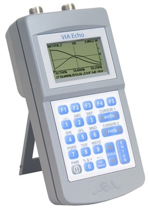
Technical Background

FDR is similar to time-domain reflectometry (TDR).  In TDR, the analyzer transmits a pulse or step and monitors the reflections in the time domain.  In FDR, the analyzer measures the return loss (amount of reflected signal) at various frequencies in a range.  It takes the inverse fast fourier transform (IFFT), which converts this frequency response into a time domain impulse response. 


An amazing fundamental fact behind DSP is that if you convolve any signal with a linear time-invariant system’s impulse response, you get its output.  The impulse response is just the output of the system when the input is an impulse.  The other amazing fundamental fact of DSP is that taking the Fourier Transform of a system’s impulse response provides the system’s frequency response.  The process works in reverse.  In FDR the analyzer knows the frequency response of the reflections.  Taking the IFFT of the frequency response gives us the impulse response.  The impulse response tells us the amplitude of the reflections from a transmitted impulse as a function of time.


Practical Testing

I tested the VIA Echo’s FDR functionality on my amateur radio antenna.  The antenna is a half wave vertical that resonates at 28MHz, fed by just under 60 feet of coax. 


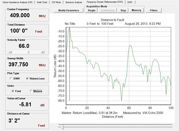
Let’s look at FDR with a sweep from 0 to 110MHz. 

image

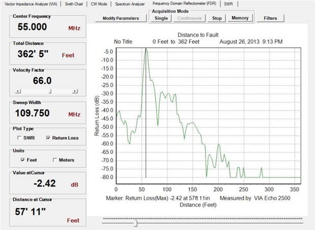
The return loss peaks at -58ft.  This is the antenna at the end of 58 feet of coax.  The peak return loss is -2.42dB, just over half the power coming back.  For a second I wondered if this means my antenna is not working.  The antenna works fine.  The sweep ran from under 1M to 110MHz.  The antenna only works in a range around 28MHz.  It reflects around half the power at most frequencies above 30MHz, and it reflects almost all power at frequencies below 20MHz.  Just over half the power being reflected is probably about right for the 1M to 110MHz.


I repeat the FDR with a sweep from 400MHz - 600MHz.

image

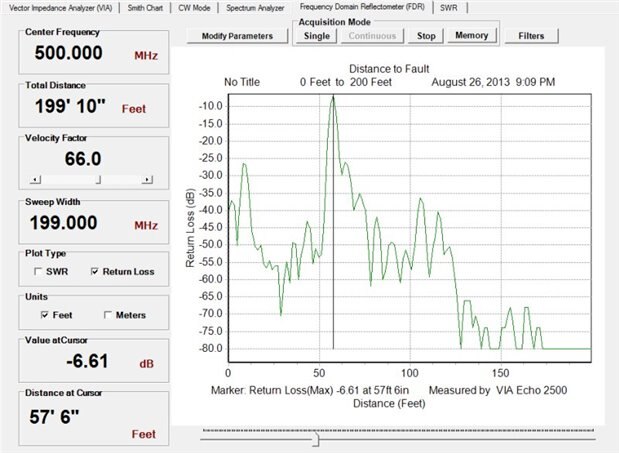
This antenna reflects power at frequencies above its resonant frequency but not nearly as much as those below it.  The peak return loss is -6.61dB, about 25%.  I suspect the antenna reflects a little more than that and the coax’s higher loss at UHF frequencies reduces return loss. 


A connector in the window that I have mounted in a plexiglass window to get the coax out of the shack, located after 8ft, is now more clearly visible.  The higher frequency helps because the connector may have more unwanted reflection at these frequencies and because of the increased spatial (time-domain) resolution you get when you use a higher sweep frequency range.


Next I place an antenna tuner rated up to 30MHz in bypass mode in the line.  I run a sweep from 0 - 110MHz.

image

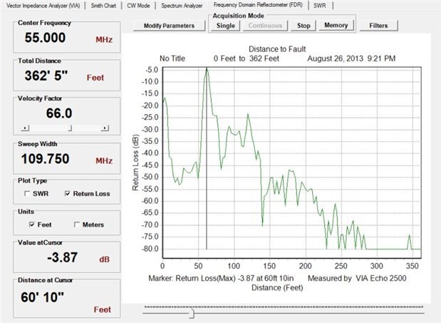
Notice the huge reflection near the beginning of the line.  This is the tuner.  It’s reflecting power because most of the sweep is outside its rated range.  Most of the power is being reflected at the tuner, so the antenna (now at just over 60ft because of the added coax going to the tuner) is a smaller peak.  It’s still easily visible.


To get more resolution, I run a sweep from 309MHz - 509MHz.  (I just wanted a higher frequency.  There’s no reason I didn’t use even numbers.  I just dialed it up.) 

image

The tuner is reflecting even more power, probably because the sweep is way outside the tuner’s rated range.  Reflection from the coupler in the window may be visible, but it’s hard to be sure because reflections from the tuner dominate.  Amazingly, reflections from the antenna itself are clearly visible still.


Conclusions

FDR is a good way to find problems or impedance transitions in feedline.  It’s a good idea to run sweeps in at least two frequency ranges in case there is a feature you want to detect that only reflects in a narrow range.  Most features reflect some across a broad range, so they will be visible regardless of the sweep range.  It doesn’t matter much whether the antenna’s resonant frequency falls within the sweep range. 


Until last year, I relied just on an SWR meter for ham radio work.  Having VNR data is useful because I can see what changes to make to the tuner to make the antenna resonant on the desired frequencies.  FDR data would be really useful there were a serious flaw in the feedline.  I would never keep a VNA / FDR analyzer around just for hobbyist work.  It’s helpful to take one home from work, though, when I have problems with my antenna. 


Further Reading

  • FDR Comparison to TDR
  • Step vs Pulse TDR Technology
  • Sign in to reply
  • gervasi
    gervasi over 12 years ago in reply to DAB

    The manual says it should work for what I'm doing.  I just found it hard to believe it actually works.  It seems like one of those things that would work in theory but not practice.


    The length of cable you can look at is a function of the sweep frequency.  The chart below is from the manual.

    image

    This just shows the plot lenght.  If the feature you're trying to see is close compared to the plot length, it will be scrunched up on the left side of the plot, so you can't see it well. 


    I'm amazed I had this equipment for a year before I tested the FDR mode.  I paid full price for it ($4300) a year ago, and I've used it on many projects.  They have less expensive versions that don't go as high in frequency. 

    • Cancel
    • Vote Up 0 Vote Down
    • Sign in to reply
    • More
    • Cancel
  • DAB
    DAB over 12 years ago

    It is amazing what you can find when you actually look beyond the expected operational parameters.


    I have seen a lot of systems undertested in regard to their performance in the real world.

    Many manufacturers just verify their operating conditions and as long as they meet those goals, they think everything is fine.


    When I was involved with a large integrated testing facility, we made sure that the system would look at the full RF spectrum of emissions from the test articles.  We found you can identify a lot of interference issues when you understand the full spectrum.

    We also ran the RF devices while transmitting a full range of RF signals.  You should have seen the results.  There were all kinds of interesting affects in some of the devices when they encountered out of band and harmonic frequencies.


    I am envious of your tools.  We had nothing like those when we were chasing down line problems.  They could have saved us a lot of time.


    You have to love the advance of technology.


    DAB

    • Cancel
    • Vote Up 0 Vote Down
    • Sign in to reply
    • More
    • Cancel
element14 Community

element14 is the first online community specifically for engineers. Connect with your peers and get expert answers to your questions.

  • Members
  • Learn
  • Technologies
  • Challenges & Projects
  • Products
  • Store
  • About Us
  • Feedback & Support
  • FAQs
  • Terms of Use
  • Privacy Policy
  • Legal and Copyright Notices
  • Sitemap
  • Cookies

An Avnet Company © 2025 Premier Farnell Limited. All Rights Reserved.

Premier Farnell Ltd, registered in England and Wales (no 00876412), registered office: Farnell House, Forge Lane, Leeds LS12 2NE.

ICP 备案号 10220084.

Follow element14

  • X
  • Facebook
  • linkedin
  • YouTube