element14 Community
element14 Community
    Register Log In
  • Site
  • Search
  • Log In Register
  • About Us
  • Community Hub
    Community Hub
    • What's New on element14
    • Feedback and Support
    • Benefits of Membership
    • Personal Blogs
    • Members Area
    • Achievement Levels
  • Learn
    Learn
    • Ask an Expert
    • eBooks
    • element14 presents
    • Learning Center
    • Tech Spotlight
    • STEM Academy
    • Webinars, Training and Events
    • Learning Groups
  • Technologies
    Technologies
    • 3D Printing
    • FPGA
    • Industrial Automation
    • Internet of Things
    • Power & Energy
    • Sensors
    • Technology Groups
  • Challenges & Projects
    Challenges & Projects
    • Design Challenges
    • element14 presents Projects
    • Project14
    • Arduino Projects
    • Raspberry Pi Projects
    • Project Groups
  • Products
    Products
    • Arduino
    • Avnet Boards Community
    • Dev Tools
    • Manufacturers
    • Multicomp Pro
    • Product Groups
    • Raspberry Pi
    • RoadTests & Reviews
  • Store
    Store
    • Visit Your Store
    • Choose another store...
      • Europe
      •  Austria (German)
      •  Belgium (Dutch, French)
      •  Bulgaria (Bulgarian)
      •  Czech Republic (Czech)
      •  Denmark (Danish)
      •  Estonia (Estonian)
      •  Finland (Finnish)
      •  France (French)
      •  Germany (German)
      •  Hungary (Hungarian)
      •  Ireland
      •  Israel
      •  Italy (Italian)
      •  Latvia (Latvian)
      •  
      •  Lithuania (Lithuanian)
      •  Netherlands (Dutch)
      •  Norway (Norwegian)
      •  Poland (Polish)
      •  Portugal (Portuguese)
      •  Romania (Romanian)
      •  Russia (Russian)
      •  Slovakia (Slovak)
      •  Slovenia (Slovenian)
      •  Spain (Spanish)
      •  Sweden (Swedish)
      •  Switzerland(German, French)
      •  Turkey (Turkish)
      •  United Kingdom
      • Asia Pacific
      •  Australia
      •  China
      •  Hong Kong
      •  India
      •  Korea (Korean)
      •  Malaysia
      •  New Zealand
      •  Philippines
      •  Singapore
      •  Taiwan
      •  Thailand (Thai)
      • Americas
      •  Brazil (Portuguese)
      •  Canada
      •  Mexico (Spanish)
      •  United States
      Can't find the country/region you're looking for? Visit our export site or find a local distributor.
  • Translate
  • Profile
  • Settings
1 Meter of Pi
  • Challenges & Projects
  • Design Challenges
  • 1 Meter of Pi
  • More
  • Cancel
1 Meter of Pi
Blog Mushrooms' Paradise #9. Raspberry PI controlled components review in detail. Part 1
  • Blog
  • Forum
  • Documents
  • Polls
  • Files
  • Events
  • Mentions
  • Sub-Groups
  • Tags
  • More
  • Cancel
  • New
  • Share
  • More
  • Cancel
Group Actions
  • Group RSS
  • More
  • Cancel
Engagement
  • Author Author: ilvyanyatka
  • Date Created: 30 Dec 2020 2:45 AM Date Created
  • Views 1111 views
  • Likes 5 likes
  • Comments 0 comments
  • 1meterofpi
  • raspi
  • 1 meter of pi
  • 1 meter of pi - design challenge
  • raspberry pi
  • mushrooms' paradise
  • growing mushrooms
Related
Recommended

Mushrooms' Paradise #9. Raspberry PI controlled components review in detail. Part 1

ilvyanyatka
ilvyanyatka
30 Dec 2020

The whole Mushrooms' Paradise blog


    • Power supply
    • Raspberry PI
    • Enviro HAT
    • Humidifier components.
    • Fan components.
    • LED strips.

image


Power supply


The power supply is an ATX PSU with 24-pin cable.  The power connector pinout

image

Detailed description can be found here: ATX Power Supply Pinout and Connectors. Basically all back wires are Ground, yellow - 12V, Orange - 3.3V, Red - 5V. Note: green wire - PS_ON needs to be connected to the Ground for  the power supply to work.


Raspberry PI


First, I glued on 4 small heat sinks because my PI will be always on. I got regular PI heat sinks from Amazon.

RPI pinout with a short guide to all type of pins of can be found here: Raspberry Pi GPIO Pinout: What Each Pin Does on Pi 4, Earlier Models

I used 3.3V supply for relays from Raspberry PI itself so the signal and 3.3V are connected to the ground in the same circuit.


Enviro HAT

I didn’t snap it onto the Pi as intended but connected all 12 pins using jumper wires. Description on how to connect them can be found here: Aquaponics Box: #2 - Hacking the HATs (both HAT... | element14 | 1 Meter of Pi.  The image below is from the same blog entry, from 1 m3 of PI Design Challenge. Green pins and pins marked with red dots are not used by Enviro.


image

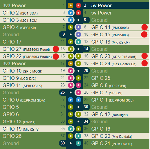
In addition to these pins 5V (pin 2) and ground (pin 6) are connected to Enviro. Enviro HAT doesn't need 3.3v connection because it has built-in 5v to 3.3v converter.


So the list of the pins connecting Raspberry PI  to Enviro HAT: 2, 6, 12, 26, 32, 38, 3, 5, 19, 21, 23, 35


Enviro HAT was actually disappointing. When it was snapped on RPI both temperature and humidity reading were off. Temperature was a couple degrees higher and humidity was 90% instead of 30%. But even if the data was right I still need to connect Enviro by jumpers, because I need access to several other pins.


Humidifier components.


The USB Humidifier is connected to IOT Relay “Normally Off” outlet. IOT Relay is controlled by GPIO pin 16 and Ground. The IOT relay is used so I don’t have to cut humidifier wires. I feel uncomfortable tinkering with 110V wires. The description of the IOT relay can be found here: IoT Relay.

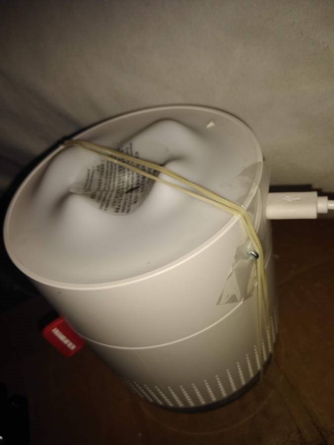
There is nothing special to say about the humidifier itself - It was the cheapest USB model I found on Amazon. The humidifier doesn’t have a switch, but a push button. So as soon as current stops it will turn off and will not turn on until the button is pushed even if there is current. To avoid this problem I used 2 rubber bands and 1 small screw to keep the button always pushed in. If I will need to get another one in the future, I will make sure it has an ON/OFF switch.


image


Fan components.

I have 3 12V 120mm computer case fans. All are powered by one relay, and are connected in parallel. The 3.3V relay is using 3.3V, ground and GPIO pin 27 (as a signal) from RPI.  12V supply for the COM port is connected to the PSU. Ground from the PSU is connected to all fans.


LED strips.

I have 3 5V 5m LED strips. All are powered by one relay, connected in parallel. 3.3V relay is using 3.3V, ground and GPIO pin 22 (as a signal) from RPI. 5V supply for the COM port is connected to the PSU.  Ground from  the PSU is connected directly to all fans.


To be continued

  • Sign in to reply
element14 Community

element14 is the first online community specifically for engineers. Connect with your peers and get expert answers to your questions.

  • Members
  • Learn
  • Technologies
  • Challenges & Projects
  • Products
  • Store
  • About Us
  • Feedback & Support
  • FAQs
  • Terms of Use
  • Privacy Policy
  • Legal and Copyright Notices
  • Sitemap
  • Cookies

An Avnet Company © 2025 Premier Farnell Limited. All Rights Reserved.

Premier Farnell Ltd, registered in England and Wales (no 00876412), registered office: Farnell House, Forge Lane, Leeds LS12 2NE.

ICP 备案号 10220084.

Follow element14

  • X
  • Facebook
  • linkedin
  • YouTube